This thread has been locked.

If you have a related question, please click the "Ask a related question" button in the top right corner. The newly created question will be automatically linked to this question.

DAC8750EVM: EVKit with NO DOCUMENTATION

Part Number: DAC8750EVM
Other Parts Discussed in Thread: DAC8750, DAC8760, REF02, , DAC8760EMC-EVM

Hi,

 so bought EVM from mouser, comes with no disk... OK, go to TI website.. not easy to find but eventually found it ( I think) sboc432b.zip

Now, if you try to get documentation for that board... you can't. On TI website.

It goes to different versions of boards and SW.

edit: SBAU205A , apparently this is the one. The 2014 update does not work.

So I am stuck and can't get it to work also for a 4-20mA current loop output, no modulation for an analog control sensor.

Edit: still cannot make it work...

Thx

NunoCL

  • Nuno,


    For the documentation, you have found the correct user's guide and software. As you mentioned, the documents are:

    User's Guide: SBAU205A
    Software SBOC432B.zip

    I would admit the user's guide is a little confusing as it was written for both the DAC8760 and DAC8750 EVMs. The guide does cover more of the DAC8760 than the DAC8750. However, the EVM and software should work similarly and there isn't a reason the EVM shouldn't work.

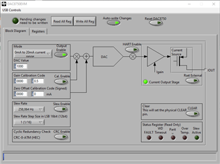
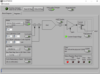
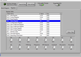
    For most applications, I'll enable the EVM, attach a load and check to see that the communication works by writing a DAC value. For this EVM, I set the Auto-write Changes (top of the GUI) so that any commands that I send are automatically updated by the EVM. I then set the Mode, enable the Output, and then set a non-zero DAC Value. You should be able to measure the output directly at J5, when JP5 is installed. The output current flows across R4 on the EVM.

    This is how it looks in my GUI.

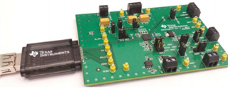
    After that, I'd check the physical connections. This is how it would look (normally you would have an external supply):

    The TI Logo on the SM-USB-DIG should be on top. Also, the EVM and the controller connections aren't keyed, so you must make sure that the pins for each side are properly aligned. The EVM does require external supplies. There is connection for AVDD and AVSS (if your AVSS is not ground).

    Also, the DVDD has two options. The first option is that you can use the AVDD to generate the device's DVDD for operation and communication. A second option is to use an external DVDD. The user's guide outlines the DVDD connections in section 3.5.2. I generally use the AVDD to generate the DVDD through the device, and JP9 would be open.

    If you continue to have problems with the EVM, can you please show me what you EVM GUI looks like, how you have the EVM setup (with maybe a photo of the EVM, and how you have it connected?

    Joseph Wu

  • I have 

    JP9

    JP3

    I have AVSS to AVDD 24V

    INTERNAL REF or REF02 (tried both) JP4 1-2 or 3-4

    NO BOOST (tried with boost also) JP5

    JP6 so that I close the loop and measure IOUT (I use a high precision DMM in current mode) Shows at 24V 63mA... too high

    It is setting alarm, Iout. As if it could not control Iout but If JP6 is installed... that should never happen... 

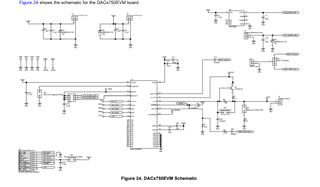
    See sch and SW config

  • Hi Joseph, 

    thanks for your reply. 

    Did all that. Communications are OK also. Checked SPI bus and all perfect. Write/Read also match.

    Supplies all OK also.

    I can't get Iout as expected.

    I also loaded a known good device that works with 4-20mA (not digital com, but analog controller) and same. 

    Thx

    NunoCL

  • I wonder if I am suffering from this same problem:

    (+) DAC7750EVM: Help to config output current - Data converters forum - Data converters - TI E2E support forums

    It would be bad... if device is dead out of the box....

  • Nuno,

    It is unlikely that the device is damaged out of the box. There is a test procedure for these EVMs and the boards are tested just after assembly. However, I can't completely rule it out.

    With JP9 and JP3, you have the DVDD supply coming from the SM-USB-DIG, so you shouldn't have different external DVDD supply.

    Can you measure the impedance across R4 just to make sure it's not shorted to ground somehow? I would also try to measure the impedance from IOUT to ground also (this time with the power supplies off).

    Just like the other post, why don't you follow the same procedure. I copied the same questions from the post, and I would check for these currents and voltages. 

    1. What is the AVDD supply current after power up before writing any commands? It should be 2-4 mA depending on the source for the DVDD supply.

    2. Is JP3 installed? If installed, then an external DVDD needs to be provided at J1 or JP9 needs to be installed. If JP3 is not installed, then JP9 should be uninstalled as well and no power should be provided at J1. (skip this part - I guess you have JP9 and JP3 installed).

    3. Confirm REFOUT=5V by measuring pin 6 of JP4.  Confirm REFIN=5V by measuring pin 1 of JP4.

    It looks like you have the same fault indicator in the GUI with the status register reading 04h, this indicates that IOUT is open and there is no resistive path to GND. This would be the case if you have no shunt in JP6. However, you mentioned that you get 63mA when JP6 is installed. You you get this current when the output is disabled? Is 63mA coming from IOUT, or is this the supply current?

    Joseph Wu

  • I tend to agree with you :) Been on that same industry as you.

    DVDD is not externally supplied. Correct. I have JP9 which connects to USB supply, and JP3 to disable internal. I tried also internal, which gives less voltage than the 4.99V from USB.

    R4 is not shorted for sure. 300Ohm

    Iout to GND is 18M, which should be OK.

    AVDD with VDD at 5V is 1.6V

    AVDD current at power up with JP6 on or off is 3.2mA@24V  avdd

    if turn OutputEnable it jumps to 63mA and not stable.

    If I measure Iout, that is similar current, so it seems that feedback just died... it puts max current and does not control it?

    VREFOUT is also 4.98

    I have HART bit disabled. JP2 no jumper in there

  • Nuno,

    Just to make sure, can you take a picture of the EVM with all your connections? I just want to be able verify the jumpers visually, and check to see how you have the power connected. Do you have AVSS connected to GND? Or do you use some sort of bipolar supply? Then can you check the current draw when you drop the supply to 12V. 

    With the output connected to a load, the EVM shouldn't really draw that much current, and I'm not sure how it could. Feedback is internal, so it shouldn't die or set a different value. 

    Just to check, did you order this EVM from TI, or from one of the distributors?

    Joseph Wu

  • failing part. swapped and works fine now. tried 8750 and 7750

    I am the second one with this problem... so is the part that sensitive or evm missing necessary protections?

  • Nuno,


    Certainly the DAC8750EVM could be damaged by an ESD event, so you should take precautions in handing the EVM. There are no specific ESD protections on the board except those integrated into the device.

    Damage may be possible if the supplies have a very fast ramp of about 1V/ns, similar to hot-swapping the part into a supply with a high current load or capacitance with a low ESR that is already charged. There may also be other potential for damage when the output is high and the load is opened. If there is some inductance in the line, this could have significant changes in voltage because of the inductive voltage change from LdI/dt, which could cause the output to go beyond the absolute maximum ratings.

    Because of the nature of these industrial environments, we recommend using the protection that we describe in the datasheet in the applications section. Unfortunately, we didn't really implement much of that in the EVM. There is however, the DAC8760EMC-EVM, which does have more of the protection integrated into the board. The DAC8760 is similar to the DAC8750, but has a voltage output as well.

    I'll close this post for now, but if you have further comments, post back and we can continue to work on this device.


    Joseph Wu