This thread has been locked.

If you have a related question, please click the "Ask a related question" button in the top right corner. The newly created question will be automatically linked to this question.

ADS1158: ADS1158 Initialize Issue

Part Number: ADS1158

We are using two no's of the ADS1158 in a medical product for data acquisition. We have made 30 no's of Pre-DVT units and below issues, we found in the units.

1. In 5 units the ADCs are not initializing properly( out of 30 units).

2. This issue is coming randomly in any one of the 2 ADCs.

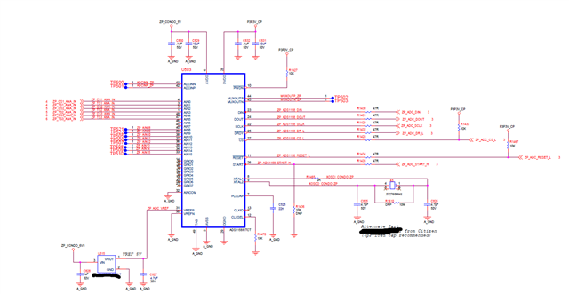
3. I have attached the board schematic below ( both ADCs are having the same circuit)as well.

  • Hi Murugavel,

    Can you explain what "not initializing properly" means? Does this mean the registers are not writing correctly, that the ADC doesn't start at all, or something else?

    We typically see many issues with customers using crystals with the ADS1158. You can search the E2E forum and find many different posts about this issue. It can take some effort to tune the oscillator circuit to make sure the crystal starts up, and this is highly system and layout dependent i.e. there is no one solution that works for everyone. If you are having this issue, I would suggest switching to a discrete clock oscillator instead of a crystal.

    -Bryan

  • Hi Bryan,

    Thanks for the reply.

    Not Initialize- Our firmware is detecting some assertion (error) conditions with ADS1158 on few boards during the process. I mean when are running the recharger process (main function of the product), somewhere in between we have started observing that firmware is detecting “NO DATA READY” condition even after waiting for 100mS. It is happening randomly and currently detected on few units which are utilized for full recharge functionality.

    Please find the waveform below of power signals 

    Green line indicates: Reset of the ADC

    Yellow line indicates: ZO_CONDO_5V( 5V rail for ADC’s Analog voltage)

    Pink line indicates:  P3P3V_CP(3V rail for ADC’s  Digital voltage)

    Blue line Indicates: 24V input

    Which depicts, ADC turned ON before the 24V supply is getting stable.

    Also, I thought reset signal doesn't have enough time constant.

    Kindly provide your thought on this.If the time constant would make any issue. pls provide an appropriate solution.

    Regards,

    Murugavel.S

  • Hi Murugavel,

    I am a bit confused as to what your issue is here. The power supplies appear to be ramping appropriately, and RESET is an input to the ADC. So if you want to control RESET better, that would need to come from a GPIO on your MCU (or something similar). Also, the device issues a power-on reset signal, so you should not need to issue your own (unless you choose to). This is described on page 22 of the ADS1158 datasheet.

    What does "No data ready" mean in your system? What is this fault condition related to?

    -Bryan