This thread has been locked.

If you have a related question, please click the "Ask a related question" button in the top right corner. The newly created question will be automatically linked to this question.

ADS1292: daisy chain ADS1292

Part Number: ADS1292
Other Parts Discussed in Thread: ADS1299

Hello,

I want to connect 3 ADS1292 in daisy chaining.

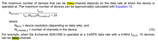
1) Would there be any limits on the clock frequency or SPS? You give an answer for the ADS1299 (see below screenshot of ADS1299 datasheet), but no comment on it for the ADS1292.

2) How would the data output look like? Would it be for instance: STAT1-CH1-CH2-STAT2-CH3-CH4-STAT3-CH5-CH6 with STATn the STAT corresponding to device n?

Also how do I know the order of the channel between the slaves? I assume the ADS1292 master STAT and channels would be first to be sent (and that all devices the respective CH1 is before the CH2) but how does the master can differentiate which slave should be the second or third to send data? In other words following example above, would it be: STAT1-CH1-CH2-STAT2-CH3-CH4-STAT3-CH5-CH6 or STAT1-CH1-CH2-STAT2-CH5-CH6-STAT3-CH3-CH4?

3) Concerning the RLD, I would like to use two separate RLD:  one on the master and one on a slave. I want to do it this way because the ADS1292 master and its electrodes are not placed in one ear, whereas the two ADS1292 slave and their electrodes are placed in the other ear. Thus I don't want a common RLD for all of them. I want a RLD for both ADS1292 slave and a RLD for the ADS1292 master. I don't see how this could be an issue, but I prefer to ask to be sure.

Best regards

  • Hi Alexis,

    Thanks for your post. Please see my comments below.  

    1 & 2) The ADS1292 supports only the multiple device configurations mode (Fig 34 of ADS1292 datasheet) and not the daisy-chain configuration mode (Figure 70b of ADS1299 datasheet). Please note that there is no such pin as DAISY_IN for the ADS1292 to facilitate the daisy-chain operation.

    3) The primary function of the RLD is to improve the CMR (Common-Mode Rejection) of the ECG/EEG system. It also serves to bias the patient to establish the common-mode voltages for all the inputs. We recommend using the RLD connection for multiple devices, as shown in Figure 41 in the datasheet.

    Thanks

    -TC

  • Hi TCT,

    I am aware of all this (ok I did not use the right term, it is multiple device configuration mode).

    Can you answer more specifically to my question? Or I should determine this by testing? 

    Thanks

  • Hi Alexis,

    Sorry if I misinterpret your questions. Would you please let me know if the below comments help to answer your questions?

    1) Are you referring to the device clock frequency and SPS or the SPI SCLK frequency? The equation for the ADS1299 is used explicitly for the daisy-chain implementation. However, you can use it as an estimation for the ADS1292 if you are using multiple devices. There is a slight difference for the multiple device configurations for the ADS1292, as you will need to use the CSB to retrieve data from each device separately. There is some additional timing requirement for the CSB and SCLK signals which is listed in Table 6.6 of the datasheet.

    2) Can you please elaborate as I am not clear on your explanation? For the standard multiple device configurations, you will need to retrieve the data from the device separately using the CSB signal from the host processor. The device data output format will always be STAT-CH1-CH2.

    Thanks

    -TC

  • Hi TC,

    1) first point is clear

    2) As in Figure 34 of datasheet, I have left all DRDY pin floating except one that I have connected to the microprocessor. It means the data output of all ADS1292 will be given on only one DRDY pin. It is also written in the datasheet that DRDY is independent of CS (see section 8.5.1.6 in datasheet). Thus this contradicts what you mmean which would be: put CS1 low to get STAT1-CH1-CH2 then put CS2 low to get STAT2-CH3-CH4 and so on, right?

    3) I want to use RLD driver for the two ADS1292 on the left ear and another RLD driver for the ADS1292 on the right ear. This is because they are not subject to the same common mode (because there is Bluetooth antenna on the right ear) and they are far away.

    Thanks

  • Hi Alexis,

    Please see my comments below for the question 2 and 3.

    2) It is correct that the DRDY is independent of CSB signal. The device's DRDY will transition low to indicate the data is ready for retrieval. For Figure 34 of the datasheet, you only need to use one DRDYB signal to the host microprocessor since all the ASD1292 devices are synchronized through the START pins. When the devices are synchronized, one DRDY is sufficient to indicate the data is ready for retrieval for all the ADS1292 devices on the SPI bus. It is up to the host processor to issue the particular CSB to access the data.

    3) I think it should be fine as the electrodes are all local to the particular RLD drive, as you mentioned.  

    Thanks

    -TC

  • Hi TC,

    3) is also clear now, thanks.

    2) So given the RDATAC SPI diagram below for 1 device

    I would have three CSB lines. I read in following order the output data of device 1, 2 and 3.

    I get the idea that I would set CSB1 line down (while CSB2 and CSB3 high) to get STAT1-CH1-CH2, then I would set CSB1 high and CSB2 low to get STAT2-CH3-CH4 and so on....

    But how would DRDY behave? Would it go up at the first falling edge of SCLK when CSB1 is low (case 1 and 2) or would it wait for the first falling edge of SCLK when CSB3 is low (case 3). If it goes up at the first falling edge of SCLK whatever I have still the output data of other devices to retrieve, then would it get low again when getting the output data of the current device (if no case 1, if yes case 2)?

    I ask this to know how I could trigger the CSB lines: either with timer counting the time to get data output of one device (case 1 and 3) or every time I get an interrupt from DRDY I would change the CSB line that has to be down (using a counter from 1 to 3)?

    Maybe a diagram would help to clarify.

    Thanks

  • Hi Alexis,

    Please note that the DRDY and all the SPI signals behave precisely as the RDATAC diagram you shown.  When CSB is taken high, the serial interface is reset, so there is no SPI communication for that particular device. This is the reason why you can share the SPI bus (SCLK, DIN, DOUT) in the multiple-device configuration. Please see a top-level example of how you can capture the data for three devices below.

    DRDY (Device #1) will trigger data retrieval interrupt IRQ function of the host processor. The IRQ function will initiate the data retrieval sequences below. The sequence is not critical in this case as the data for all the devices is ready for retrieval in a synchronous system.

    1. Set CSB1 low, send SCLK to retrieve data from device #1, set CSB1 high. DRDY (Device #1) will go high on the first SCLK falling edge in this sequence.
    2. Set CSB2 low, send SCLK to retrieve data from device #2, set CSB2 high.
    3. Set CSB3 low, send SCLK to retrieve data from device #3, set CSB3 high.

    All the 3 data retrieval steps above need to be completed before the next IRQ for the continuous interrupt process.

    Thanks

    -TC

  • Hi TC,

    Thanks for the clear explanation

  • Hi Alexis,

    Please let us know if you need further assistance. 

    Thanks

    -TC