This thread has been locked.

If you have a related question, please click the "Ask a related question" button in the top right corner. The newly created question will be automatically linked to this question.

AFE4300: Problem with SPI Communication

Part Number: AFE4300

Hello,

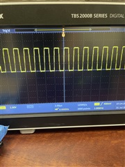
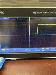
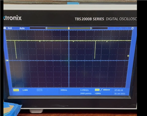
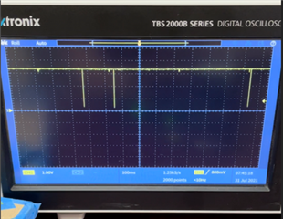
I am trying to connect an AFE4300EVM to a nRF5284-DK using the evaluation module's SPI interface. By detaching the MMB3 board from the AFE4300EVM and wiring the pins of J103 to the correct GPIOs of the nRF52840 development kit, I can connect the two boards together. I am able to write to the AFE4300's registers, which was tested by checking the voltage of VLDO after enabling the weight scale chain. However, I'm facing an issue when trying to read from any of the registers, including ADC_DATA_REGISTER. The RDY signals begins in a high state, pulses low for 8 microseconds as each register is written to, and finally remains high / does not interrupt after writing to the registers.

My questions are:

1) Why does the RDY signal begin high, while Figures 10 and 11 of the datasheet indicate that RDY should start low?

2) Should I be monitoring the RDY signal while writing to the registers or only while reading?

3) If RDY's brief low pulse signifies the end of a conversion, should I be prepared to immediately read the data after the last register write, or can I prevent the interrupt/data conversion from occurring right away? 

4) Does STE serve any purpose if the AFE4300 is the only slave device on the serial bus?

  • Hello Yamen,

    Please confirm if, after power up, you are programming some of the reserved bits of the registers to the recommended values in the datasheet.

    In addition to checking the VLDO voltage, you can also verify if the SPI writes work by checking the VREF voltage.To verify VREF voltage (assuming device is out of reset), you will only need to write to DEVICE_CONTROL1 register address (0x09) value of 0x6006 after power-up and reset. In this case, you should measure 1.72V on TP4 on the AFE4300 EVM.

    If SPI writes work properly, then you can check the SPI reads.

    Check the SPI timing diagram and see the timing edges conform to the datasheet description. For example, the device latches data on SDIN on the falling edge of SCLK. During read, data is shifted out on the SDOUT pin on the rising edge of SCLK. Also note that every time a register is read, the register must be rewritten except when reading the data output register.

    For other register access reads, you do not need to monitor the RDY signal.

    Regarding STE, our recommendation is to keep the STE low for only 1 SPI transaction. Do not tie STE low.

    Doing multiple SPI transactions with STE pulled low is not recommended. This is contrary to what the datasheet recommends. We will try to fix this in the next rev of the datasheet.

  • Hi,

    I was able to get the SPI communication working correctly, but I'm facing some issues when continuously reading from the ADC_DATA_RESULT register. As you can see in the screenshot below, the read data is quite inconsistent when there is no load present. Then, after about 30 seconds of reading from the register, the data becomes zero, as if the AFE4300 times out. I do not monitor the RDY signal in my code.

    Here are the values I write to the registers after reset:

    write_reg(ADC_CONTROL_REGISTER1, 0x4140);
    write_reg(MISC_REGISTER1, 0x0000);
    write_reg(MISC_REGISTER2, 0xFFFF);
    write_reg(DEVICE_CONTROL1, 0x6005);
    write_reg(ISW_MUX, 0x0000);
    write_reg(VSENSE_MUX, 0x0000);
    write_reg(IQ_MODE_ENABLE, 0x0000);
    write_reg(WEIGHT_SCALE_CONTROL, 0x0000);
    write_reg(BCM_DAC_FREQ, 0x0000);
    write_reg(DEVICE_CONTROL2, 0x0000);
    write_reg(ADC_CONTROL_REGISTER2, 0x0000);
    write_reg(MISC_REGISTER3, 0x0030);

    Any suggestions to fix the inconsistency and timeout? Thank you.

  • Hello Yamen,

    The register controls look fine. I verified on the AFE4300 EVM and able to receive continuous data at 128sps. Can you probe the RDY signal for continuous pulses at ~128Hz?

    Additionally to check for continuous data, you can also put the device into battery monitoring mode and check if you are receiving AVDD/3 as ADC data.

    Here is the register setting for placing the device in battery monitoring mode.

  • Hello,

    The RDY signal pulses at ~256 Hz when the ADC conversion rate is configured to 128 sps. The same trend occurs when the other sample rates are tested -- the pulse frequency is roughly double the sample rate.

    I put the device into battery monitoring mode and received more consistent results, as shown below.

    Any ideas?

  • Hi,

    The programmed data rate is based on the input clock frequency of 1MHz. Please check the AFE input clock frequency.

  • Hello,

    Below are the results I obtained upon probing the CLK_MCU signal with my oscilloscope. As you can see, the input clock frequency is 1 MHz.

  • Yamen,

    Can you please attach the RDY signal waveform as well for 128 sps DR?

  • Hello,

    Attached below is the RDY signal waveform when the sample rate is configured to 128 sps.

  • The RDY signal only shows 1 pulse. Can you zoom out and show multiple pulses?

  • Hello,

    Attached below is a video of the RDY signal with multiple pulses. Are you able to view it?

    Click here to play this video

  • Hi,

    I am unable to view the video from Google Chrome browser.

    As you had shown previously, you can insert an image of the waveform of the multiple pulses.

  • Hi Praveen,

    Here are a few screenshots from the video above.

    The first image shows two subsequent pulses of the RDY signal.

    The second image shows an event that occurs every 5 or so pulses.