This thread has been locked.

If you have a related question, please click the "Ask a related question" button in the top right corner. The newly created question will be automatically linked to this question.

ADS122C04: Current Consumption increases during conversion

Part Number: ADS122C04

Dear Specialists,

My customer is evaluating ADS122C04 and has a question.

I would be grateful if you could advise.

---

At the start of AD acquisition,

the current temporarily increased to 1 mA(max), and after about 5 to 10 seconds, the current settled down to 400uA.

VDD=2.5V

The current includes IDVDD.

Is this the normal operation of this device?

Is there a possibility of a problem with the setting method?

The setting data sent to the ADC at the start of AD acquisition is as follows.

address0:0x81, address1:0xA2, address3:0x00 and address4:0x00

---

I appreciate your great help and cooperation.

Best regards,

Shinichi

  • Hi Shinichi,

    The given configuration places the ADS122C04 in single-shot mode while using an external reference. So initially the device will be in a low-power state where most of the internals are shut down.  When the START/SYNC command is issued, the ADC will power up the internal oscillator and start the conversion.  This startup will draw some additional current but I would expect it to stabilize much sooner that 5 to 10 seconds.

    The startup and conversion will only last for about 2ms before going back to a low-power state.  So I need more information as to what is actually happening with the device and the type of measurement loop that is being run.  Also, it would be helpful to see a schematic and to know what voltage is being applied to the inputs as well as the reference voltage used.

    It is not clear how the current measurement is being made.  If making an indirect measurement with a resistor in series, this may cause some issues if the resistance is too large.  Any inductance or ferrites in the supply path may also cause issues as there are times that the ADC will require large currents for very short intervals.  If the current is being limited or choked, this may also cause some issues.

    Best regards,

    Bob B

  • Hi Bob,

    Thank you for your reply.

    And I'm sorry for late reply because I had summer holidays.

    I'll share your comment with the customer.

    When I obtain, I'll contact again.

    Could you please wait for a while.

    I appreciate your great help and cooperation.

    Best regards,

    Shinichi

  • Hi Bob,

    I'm sorry for late reply. Because the customer encountered another problem.

    I could obtain the detail,  so could you please confirm and advise.

    --- 

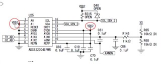
    The circuit is the same as the datasheet.

    Could you please see the image listed below.

    It supplies an external power supply (2.5V) directly.

    I added a capacitor(470uF) to the output of the external power supply and checked it , but there was no difference in the result.

    The current was measured with an original measuring jig.

    Measurements were also carried out with a power analyzer (WT1801E Yokogawa).

    The result was the same, and the symptom that the current increased shortly after the start of sampling was confirmed.

    We have acquired data on the relationship between power supply voltage and current consumption.

    Please check the attached image.

    4064.AD122C04 current waveform.xlsx

    The current consumption increases at the same time as the conversion starts, and after 10 seconds, the current further increases and then decreases.

    Is it a normal operation?

    For comparison, I'd like you to perform the same measurement.

    ---

    I appreciate your great help and cooperation.

    Best regards,

    Shinichi
  • Hi Shinichi,

    For me to try and replicate, I need to know precisely how the current is being measured.  Is the measured current localized to just the ADC or is it the total current from the 2.5V supply?

    Second thing I need to know is the device configuration.  What are the register settings for the device when the current is being measured?

    Last thing that would be helpful would be to know precisely what is being connected to the analog inputs at the time the issue is seen?  What is VS?

    The overall power consumption may not be that far out of what would be expected depending on the device configuration.  The current jump is unusual, but I suspect that may have something to do with either the configuration or what is connected to the inputs.

    Best regards,

    Bob B

  • Hi Bob,

    Thank you for your reply.

    I conform the customer the questions you asked.

    When I obtain, I'll sent to you.

    Could you please wait for a while.

    I appreciate your great help and cooperation.

    Best regards,

    Shinichi 

  • Hi Shinichi,

    No problem.  I understand getting the answers to questions can take a while.  I will await the further information.

    Best regards,

    Bob B

  • Hi Bob,

    I'm sorry for late reply.

    I could obtain the answer from the customer.

    Could you please see below.

    ---

    (1) 2.5V power supply is connected only to the ADS122C04.

    (2) address0: 0x81, address1: 0xA2, address3: 0x00 and address4: 0x00
    This register setting is repeatedly set for each sampling (cycle is 100ms).

    (3) VS is the supply voltage to the sensor. The voltage is a divided value of 2.5V, so it is about 1.5V.

    In the figure I gave you last time, I explained that the timing when the current started to increase was "AD sampling start".

    It was a mistake of "starting power supply to IC".

    The correct timing for the current to increase is "about 10 seconds after the power is turned on to the IC".

    In order to confirm whether the sampling start and the current increase are linked, I altered software that does not perform conversion at all (does not send commands) and monitored the current value.

    As a result, the current waveform is the same.

    Therefore, starting sampling is not a factor in increasing the current.

    The current consumption is increasing when the power is turned on.

    Will this phenomenon be reproduced by EVM?

    Could you please let me know the cause of this.

    ---

    I appreciate your great help and cooperation.

    Best regards,

    Shinichi

  • Hi Shinichi,

    I will look into this as soon as I can, but most likely will not have an answer until the middle of next week.

    Best regards,

    Bob B

  • Hi Shinichi,

    I measured the currents using a DMM in current measurement mode so the direct current measurement is going to be an average.  I did not see any issues when powering the ADS122C04.  I then set the register settings to the same values used by the customer.  I cannot setup the EVM to use measurement periods of 1ms, so as soon as one conversion is complete I read the conversion and then start the next conversion immediately.

    The analog current when not converting is about 0.1uA and after conversion starts is about 284.4uA and steady.  I do not see this current changing.  This is actually slightly better than what is shown in the datasheet with 250uA (with PGA disabled) + 60uA (with the external reference connected).  The digital current 0.27uA when not converting and 71.23uA when converting.  These values are measured using 3.3V supplies.

    I do not see the long drift characteristics or higher currents as demonstrated by the customer.  The customer may have some issues with some unaccounted for capacitance or current drawn through some other device that requires settling.  A more complete schematic and board layout would help me to analyze the issue further.

    So as an overview, if the ADS122C04 is powered  and the device is not converting, the ADS122C04 will be in a low power state.  You should not see any current being drawn by the ADC that is more than a few uA.  If there are larger currents and settling that is taken place this may be caused by some other source.  For example, the micro maybe pulling current through the I2C bus unexpectedly.

    I would suggest limiting any voltage connection to each of the ADC device pins to include analog and digital pins until the reason for why the current is having this odd behavior.  I would start with verifying the I2C connections as it is unclear how the micro is communicating to the bus if the only connection for the 2.5V is to the ADC.

    Best regards,

    Bob B

  • Hi Bob,

    Thank you for your reply and confirm the EVM.

    I understand no current increase was observed when ADS122C04 was turned on.

    I'll share this information with the customer and look into the influence from the other pins include input(analog) and output(digital).

    When I obtain any information, I’ll inform you.

    I appreciate your great help and cooperation.

    Best regards,

    Shinichi