Hi,
Please find the code and schematic below. For channel0, I am able to read the digital data. But when I am changing the analog channel to to channel1, I am not able to read channel1 data. I am getting the same channel0 data even if channel configuration is made for channel 1.
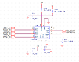
Sch is attached

1. Code for channel 0 confg:
a) Header file
/* SYSTEM_STATUS register */
#define SYSTEM_STATUS_ADDRESS 0x00
#define SYSTEM_STATUS_DEFAULT 0x80
/* SEQ_STATUS field */
#define SEQ_STATUS_MASK 0x40
#define SEQ_STATUS_STOPPED 0x00 // DEFAULT
#define SEQ_STATUS_RUNNING 0x40
/* I2C_SPEED field */
#define I2C_SPEED_MASK 0x20
#define I2C_SPEED_NORMAL 0x00 // DEFAULT
#define I2C_SPEED_HIGH 0x20
/* OSR_DONE field */
#define OSR_DONE_MASK 0x08
#define OSR_DONE_WAITING 0x00 // DEFAULT
#define OSR_DONE_COMPLETE 0x08
/* CRC_ERR_FUSE field */
#define CRC_ERR_FUSE_MASK 0x04
#define CRC_ERR_FUSE_OKAY 0x00 // DEFAULT
#define CRC_ERR_FUSE_ERROR 0x04
/* CRC_ERR_IN field */
#define CRC_ERR_IN_MASK 0x02
#define CRC_ERR_IN_OKAY 0x00 // DEFAULT
#define CRC_ERR_IN_ERROR 0x02
/* BOR field */
#define BOR_MASK 0x01
#define BOR_OKAY 0x00
#define BOR_ERROR 0x01 // DEFAULT
/* Register 0x01 (GENERAL_CFG) definition
* |-----------------------------------------------------------------------------------------------------------------------|
* | Bit 7 | Bit 6 | Bit 5 | Bit 4 | Bit 3 | Bit 2 | Bit 1 | Bit 0 |
* |-----------------------------------------------------------------------------------------------------------------------|
* | RESERVED[3:0] | CNVST | CH_RST | CAL | RST |
* |-----------------------------------------------------------------------------------------------------------------------|
*/
/* GENERAL_CFG register */
#define GENERAL_CFG_ADDRESS 0x01
#define GENERAL_CFG_DEFAULT 0x00
/* CNVST field */
#define CNVST_MASK 0x08
#define CNVST_NORMAL_SCL_STRETCHED 0x00 // DEFAULT
#define CNVST_START_NO_STRETCH 0x08
/* CH_RST field */
#define CH_RST_MASK 0x04
#define CH_RST_NORMAL 0x00 // DEFAULT
#define CH_RST_FORCE_AIN 0x04
/* CAL field */
#define CAL_MASK 0x02
#define CAL_COMPLETE 0x00 // DEFAULT
#define CAL_START 0x02
/* RST field */
#define RST_MASK 0x01
#define RST_COMPLETE 0x00 // DEFAULT
#define RST_START 0x01
/* Register 0x02 (DATA_CFG) definition
* |-----------------------------------------------------------------------------------------------------------------------|
* | Bit 7 | Bit 6 | Bit 5 | Bit 4 | Bit 3 | Bit 2 | Bit 1 | Bit 0 |
* |-----------------------------------------------------------------------------------------------------------------------|
* | FIX_PAT | RESERVED | APPEND_STATUS[1:0] | RESERVED[3:0] |
* |-----------------------------------------------------------------------------------------------------------------------|
*/
/* DATA_CFG register */
#define DATA_CFG_ADDRESS 0x02
#define DATA_CFG_DEFAULT 0x00
/* FIX_PAT field */
#define FIX_PAT_MASK 0x80
#define FIX_PAT_NORMAL 0x00 // DEFAULT
#define FIX_PAT_ENABLE 0x80
/* APPEND_STATUS field */
#define APPEND_STATUS_MASK 0x30
#define APPEND_STATUS_DISABLE 0x00 // DEFAULT
#define APPEND_STATUS_ID 0x10
#define APPEND_STATUS_ONLY 0x20
/* Register 0x03 (OSR_CFG) definition
* |-----------------------------------------------------------------------------------------------------------------------|
* | Bit 7 | Bit 6 | Bit 5 | Bit 4 | Bit 3 | Bit 2 | Bit 1 | Bit 0 |
* |-----------------------------------------------------------------------------------------------------------------------|
* | RESERVED[4:0] | OSR[2:0] |
* |-----------------------------------------------------------------------------------------------------------------------|
*/
/* OSR_CFG register */
#define OSR_CFG_ADDRESS 0x03
#define OSR_CFG_DEFAULT 0x00
/* OSR field */
#define OSR_MASK 0x07
#define OSR_1 0x00 // DEFAULT
#define OSR_2 0x01
#define OSR_4 0x02
#define OSR_8 0x03
#define OSR_16 0x04
#define OSR_32 0x05
#define OSR_64 0x06
#define OSR_128 0x07
/* Register 0x04 (OPMODE_CFG) definition
* |-----------------------------------------------------------------------------------------------------------------------|
* | Bit 7 | Bit 6 | Bit 5 | Bit 4 | Bit 3 | Bit 2 | Bit 1 | Bit 0 |
* |-----------------------------------------------------------------------------------------------------------------------|
* | RESERVED[2:0] | OSC_SEL | CLK_DIV[3:0] |
* |-----------------------------------------------------------------------------------------------------------------------|
*/
/* OPMODE_CFG register */
#define OPMODE_CFG_ADDRESS 0x04
#define OPMODE_CFG_DEFAULT 0x00
/* OSC_SEL field */
#define OSC_SEL_MASK 0x10
#define OSC_SEL_HIGH_SPEED 0x00 // DEFAULT
#define OSC_SEL_LOW_POWER 0x10
/* Register 0x05 (PIN_CFG) definition
* |-----------------------------------------------------------------------------------------------------------------------|
* | Bit 7 | Bit 6 | Bit 5 | Bit 4 | Bit 3 | Bit 2 | Bit 1 | Bit 0 |
* |-----------------------------------------------------------------------------------------------------------------------|
* | PIN_CFG[7:0] |
* |-----------------------------------------------------------------------------------------------------------------------|
*/
/* PIN_CFG register */
#define PIN_CFG_ADDRESS 0x05
#define PIN_CFG_DEFAULT 0x00
/* PIN_CFG field */
#define PIN_CFG_MASK 0xFF
#define PIN_CFG_AIN0 0x01
#define PIN_CFG_AIN1 0x02
#define PIN_CFG_AIN2 0x04
#define PIN_CFG_AIN3 0x08
#define PIN_CFG_AIN4 0x10
#define PIN_CFG_AIN5 0x20
#define PIN_CFG_AIN6 0x40
#define PIN_CFG_AIN7 0x80
/* Register 0x07 (GPIO_CFG) definition
* |-----------------------------------------------------------------------------------------------------------------------|
* | Bit 7 | Bit 6 | Bit 5 | Bit 4 | Bit 3 | Bit 2 | Bit 1 | Bit 0 |
* |-----------------------------------------------------------------------------------------------------------------------|
* | GPIO_CFG[7:0] |
* |-----------------------------------------------------------------------------------------------------------------------|
*/
/* GPIO_CFG register */
#define GPIO_CFG_ADDRESS 0x07
#define GPIO_CFG_DEFAULT 0x00
/* GPIO_CFG field */
#define GPIO_CFG_MASK 0xFF
#define GPIO_CFG_GPO0 0x01
#define GPIO_CFG_GPO1 0x02
#define GPIO_CFG_GPO2 0x04
#define GPIO_CFG_GPO3 0x08
#define GPIO_CFG_GPO4 0x10
#define GPIO_CFG_GPO5 0x20
#define GPIO_CFG_GPO6 0x40
#define GPIO_CFG_GPO7 0x80
/* Register 0x09 (GPO_DRIVE_CFG) definition
* |-----------------------------------------------------------------------------------------------------------------------|
* | Bit 7 | Bit 6 | Bit 5 | Bit 4 | Bit 3 | Bit 2 | Bit 1 | Bit 0 |
* |-----------------------------------------------------------------------------------------------------------------------|
* | GPO_DRIVE_CFG[7:0] |
* |-----------------------------------------------------------------------------------------------------------------------|
*/
/* GPO_DRIVE_CFG register */
#define GPO_DRIVE_CFG_ADDRESS 0x09
#define GPO_DRIVE_CFG_DEFAULT 0x00
/* GPO_DRIVE_CFG field */
#define GPO_DRIVE_CFG_MASK 0xFF
#define GPO_DRIVE_CFG_GPO0 0x01
#define GPO_DRIVE_CFG_GPO1 0x02
#define GPO_DRIVE_CFG_GPO2 0x04
#define GPO_DRIVE_CFG_GPO3 0x08
#define GPO_DRIVE_CFG_GPO4 0x10
#define GPO_DRIVE_CFG_GPO5 0x20
#define GPO_DRIVE_CFG_GPO6 0x40
#define GPO_DRIVE_CFG_GPO7 0x80
/* Register 0x0B (GPO_VALUE) definition
* |-----------------------------------------------------------------------------------------------------------------------|
* | Bit 7 | Bit 6 | Bit 5 | Bit 4 | Bit 3 | Bit 2 | Bit 1 | Bit 0 |
* |-----------------------------------------------------------------------------------------------------------------------|
* | GPO_VALUE[7:0] |
* |-----------------------------------------------------------------------------------------------------------------------|
*/
/* GPO_VALUE register */
#define GPO_VALUE_ADDRESS 0x0B
#define GPO_VALUE_DEFAULT 0x00
/* GPO_VALUE field */
#define GPO_VALUE_MASK 0xFF
#define GPO_VALUE_GPO0_HIGH 0x01
#define GPO_VALUE_GPO1_HIGH 0x02
#define GPO_VALUE_GPO2_HIGH 0x04
#define GPO_VALUE_GPO3_HIGH 0x08
#define GPO_VALUE_GPO4_HIGH 0x10
#define GPO_VALUE_GPO5_HIGH 0x20
#define GPO_VALUE_GPO6_HIGH 0x40
#define GPO_VALUE_GPO7_HIGH 0x80
/* Register 0x0D (GPI_VALUE) definition
* |-----------------------------------------------------------------------------------------------------------------------|
* | Bit 7 | Bit 6 | Bit 5 | Bit 4 | Bit 3 | Bit 2 | Bit 1 | Bit 0 |
* |-----------------------------------------------------------------------------------------------------------------------|
* | GPI_VALUE[7:0] |
* |-----------------------------------------------------------------------------------------------------------------------|
*/
/* GPI_VALUE register */
#define GPI_VALUE_ADDRESS 0x0D
#define GPI_VALUE_DEFAULT 0x00
/* GPI_VALUE field */
#define GPI_VALUE_MASK 0xFF
#define GPI_VALUE_GPI0_HIGH 0x01
#define GPI_VALUE_GPI1_HIGH 0x02
#define GPI_VALUE_GPI2_HIGH 0x04
#define GPI_VALUE_GPI3_HIGH 0x08
#define GPI_VALUE_GPI4_HIGH 0x10
#define GPI_VALUE_GPI5_HIGH 0x20
#define GPI_VALUE_GPI6_HIGH 0x40
#define GPI_VALUE_GPI7_HIGH 0x80
/* Register 0x10 (SEQUENCE_CFG) definition
* |-----------------------------------------------------------------------------------------------------------------------|
* | Bit 7 | Bit 6 | Bit 5 | Bit 4 | Bit 3 | Bit 2 | Bit 1 | Bit 0 |
* |-----------------------------------------------------------------------------------------------------------------------|
* | RESERVED[2:0] | SEQ_START | RESERVED[1:0] | SEQ_MODE[1:0] |
* |-----------------------------------------------------------------------------------------------------------------------|
*/
/* SEQUENCE_CFG register */
#define SEQUENCE_CFG_ADDRESS 0x10
#define SEQUENCE_CFG_DEFAULT 0x00
/* SEQ_START field */
#define SEQ_START_MASK 0x10
#define SEQ_START_END 0x00 // DEFAULT
#define SEQ_START_ASSEND 0x10
/* SEQ_MODE field */
#define SEQ_MODE_MASK 0x03
#define SEQ_MODE_MANUAL 0x00 // DEFAULT
#define SEQ_MODE_AUTO 0x01
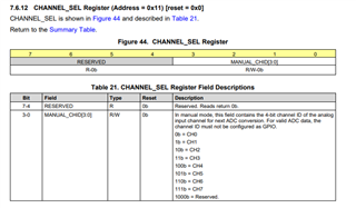
/* Register 0x11 (MANUAL_CH_SEL) definition
* |-----------------------------------------------------------------------------------------------------------------------|
* | Bit 7 | Bit 6 | Bit 5 | Bit 4 | Bit 3 | Bit 2 | Bit 1 | Bit 0 |
* |-----------------------------------------------------------------------------------------------------------------------|
* | RESERVED[3:0] | MANUAL_CHID[3:0] |
* |-----------------------------------------------------------------------------------------------------------------------|
*/
/* MANUAL_CH_SEL register */
#define MANUAL_CH_SEL_ADDRESS 0x11
#define MANUAL_CH_SEL_DEFAULT 0x00
/* MANUAL_CHID field */
#define MANUAL_CHID_MASK 0x0F
#define MANUAL_CHID_AIN0 0x00 // DEFAULT
#define MANUAL_CHID_AIN1 0x01
#define MANUAL_CHID_AIN2 0x02
#define MANUAL_CHID_AIN3 0x03
#define MANUAL_CHID_AIN4 0x04
#define MANUAL_CHID_AIN5 0x05
#define MANUAL_CHID_AIN6 0x06
#define MANUAL_CHID_AIN7 0x07
/* Register 0x12 (AUTO_SEQ_CH_SEL) definition
* |-----------------------------------------------------------------------------------------------------------------------|
* | Bit 7 | Bit 6 | Bit 5 | Bit 4 | Bit 3 | Bit 2 | Bit 1 | Bit 0 |
* |-----------------------------------------------------------------------------------------------------------------------|
* | AUTO_SEQ_CH_SEL[7:0] |
* |-----------------------------------------------------------------------------------------------------------------------|
*/
/* AUTO_SEQ_CH_SEL register */
#define AUTO_SEQ_CH_SEL_ADDRESS 0x12
#define AUTO_SEQ_CH_SEL_DEFAULT 0x00
/* AUTO_SEQ_CH_SEL field */
#define AUTO_SEQ_CH_SEL_MASK 0xFF
#define AUTO_SEQ_CH_SEL_AIN0 0x01
#define AUTO_SEQ_CH_SEL_AIN1 0x02
#define AUTO_SEQ_CH_SEL_AIN2 0x04
#define AUTO_SEQ_CH_SEL_AIN3 0x08
#define AUTO_SEQ_CH_SEL_AIN4 0x10
#define AUTO_SEQ_CH_SEL_AIN5 0x20
#define AUTO_SEQ_CH_SEL_AIN6 0x40
#define AUTO_SEQ_CH_SEL_AIN7 0x80
#define SLAVE_ADDRESS_TLA (0x13 << 1)
void adc_tla2528_test(void);
#endif /* TLA2528_H_ */
b) c source file
#include "adc_tla2528.h"
#include "string.h"
#include "usart.h"
#include "i2c.h"
uint8_t rx_buf[100];
void adc_tla2528_test(void)
{
unsigned char buff1[2];
buff1[0] = SYSTEM_STATUS_ADDRESS;
buff1[1] = SYSTEM_STATUS_DEFAULT;
unsigned char buff2[2];
buff2[0] = GENERAL_CFG_ADDRESS;
buff2[1] = GENERAL_CFG_DEFAULT;
unsigned char buff3[2];
buff3[0] = DATA_CFG_ADDRESS;
buff3[1] = DATA_CFG_DEFAULT;
unsigned char buff4[2];
buff4[0] = OSR_CFG_ADDRESS;
buff4[1] = OSR_CFG_DEFAULT;
unsigned char buff5[2];
buff5[0] = OPMODE_CFG_ADDRESS;
buff5[1] = OPMODE_CFG_DEFAULT;
unsigned char buff6[2];
buff6[0] = PIN_CFG_ADDRESS;
buff6[1] = PIN_CFG_DEFAULT;
unsigned char buff7[2];
buff7[0] = GPIO_CFG_ADDRESS;
buff7[1] = GPIO_CFG_DEFAULT;
unsigned char buff8[2];
buff8[0] = GPO_DRIVE_CFG_ADDRESS;
buff8[1] = GPO_DRIVE_CFG_DEFAULT;
unsigned char buff9[2];
buff9[0] = GPO_VALUE_ADDRESS;
buff9[1] = GPO_VALUE_DEFAULT;
unsigned char buff10[2];
buff10[0] = GPI_VALUE_ADDRESS;
buff10[1] = GPO_VALUE_DEFAULT;
unsigned char buff11[2];
buff11[0] = SEQUENCE_CFG_ADDRESS;
buff11[1] = SEQUENCE_CFG_DEFAULT;
unsigned char buff12[2];
buff12[0] = MANUAL_CH_SEL_ADDRESS;
buff12[1] = MANUAL_CH_SEL_DEFAULT;
unsigned char buff13[2];
buff13[0] = AUTO_SEQ_CH_SEL_ADDRESS;
buff13[1] = AUTO_SEQ_CH_SEL_DEFAULT;
HAL_I2C_Master_Transmit(&hi2c1, SLAVE_ADDRESS_TLA, (uint8_t *) buff1, 2, 100);
HAL_Delay(1);
HAL_I2C_Master_Transmit(&hi2c1, SLAVE_ADDRESS_TLA, (uint8_t *) buff2, 2, 100);
HAL_Delay(1);
HAL_I2C_Master_Transmit(&hi2c1, SLAVE_ADDRESS_TLA, (uint8_t *) buff3, 2, 100);
HAL_Delay(1);
HAL_I2C_Master_Transmit(&hi2c1, SLAVE_ADDRESS_TLA, (uint8_t *) buff4, 2, 100);
HAL_Delay(1);
HAL_I2C_Master_Transmit(&hi2c1, SLAVE_ADDRESS_TLA, (uint8_t *) buff5, 2, 100);
HAL_Delay(1);
HAL_I2C_Master_Transmit(&hi2c1, SLAVE_ADDRESS_TLA, (uint8_t *) buff6, 2, 100);
HAL_Delay(1);
HAL_I2C_Master_Transmit(&hi2c1, SLAVE_ADDRESS_TLA, (uint8_t *) buff7, 2, 100);
HAL_Delay(1);
HAL_I2C_Master_Transmit(&hi2c1, SLAVE_ADDRESS_TLA, (uint8_t *) buff8, 2, 100);
HAL_Delay(1);
HAL_I2C_Master_Transmit(&hi2c1, SLAVE_ADDRESS_TLA, (uint8_t *) buff9, 2, 100);
HAL_Delay(1);
HAL_I2C_Master_Transmit(&hi2c1, SLAVE_ADDRESS_TLA, (uint8_t *) buff10, 2, 100);
HAL_Delay(1);
HAL_I2C_Master_Transmit(&hi2c1, SLAVE_ADDRESS_TLA, (uint8_t *) buff11, 2, 100);
HAL_Delay(1);
HAL_I2C_Master_Transmit(&hi2c1, SLAVE_ADDRESS_TLA, (uint8_t *) buff12, 2, 100);
HAL_Delay(1);
HAL_I2C_Master_Transmit(&hi2c1, SLAVE_ADDRESS_TLA, (uint8_t *) buff13, 2, 100);
HAL_Delay(1);
HAL_I2C_Master_Receive(&hi2c1, SLAVE_ADDRESS_TLA, (uint8_t *) rx_buf, 3, 100);
}
2. code for channel 1 confg
#define SYSTEM_STATUS_ADDRESS 0x00
#define SYSTEM_STATUS_DEFAULT 0x80
/* SEQ_STATUS field */
#define SEQ_STATUS_MASK 0x40
#define SEQ_STATUS_STOPPED 0x00 // DEFAULT
#define SEQ_STATUS_RUNNING 0x40
/* I2C_SPEED field */
#define I2C_SPEED_MASK 0x20
#define I2C_SPEED_NORMAL 0x00 // DEFAULT
#define I2C_SPEED_HIGH 0x20
/* OSR_DONE field */
#define OSR_DONE_MASK 0x08
#define OSR_DONE_WAITING 0x00 // DEFAULT
#define OSR_DONE_COMPLETE 0x08
/* CRC_ERR_FUSE field */
#define CRC_ERR_FUSE_MASK 0x04
#define CRC_ERR_FUSE_OKAY 0x00 // DEFAULT
#define CRC_ERR_FUSE_ERROR 0x04
/* CRC_ERR_IN field */
#define CRC_ERR_IN_MASK 0x02
#define CRC_ERR_IN_OKAY 0x00 // DEFAULT
#define CRC_ERR_IN_ERROR 0x02
/* BOR field */
#define BOR_MASK 0x01
#define BOR_OKAY 0x00
#define BOR_ERROR 0x01 // DEFAULT
/* Register 0x01 (GENERAL_CFG) definition
* |-----------------------------------------------------------------------------------------------------------------------|
* | Bit 7 | Bit 6 | Bit 5 | Bit 4 | Bit 3 | Bit 2 | Bit 1 | Bit 0 |
* |-----------------------------------------------------------------------------------------------------------------------|
* | RESERVED[3:0] | CNVST | CH_RST | CAL | RST |
* |-----------------------------------------------------------------------------------------------------------------------|
*/
/* GENERAL_CFG register */
#define GENERAL_CFG_ADDRESS 0x01
#define GENERAL_CFG_DEFAULT 0x00
/* CNVST field */
#define CNVST_MASK 0x08
#define CNVST_NORMAL_SCL_STRETCHED 0x00 // DEFAULT
#define CNVST_START_NO_STRETCH 0x08
/* CH_RST field */
#define CH_RST_MASK 0x04
#define CH_RST_NORMAL 0x00 // DEFAULT
#define CH_RST_FORCE_AIN 0x04
/* CAL field */
#define CAL_MASK 0x02
#define CAL_COMPLETE 0x00 // DEFAULT
#define CAL_START 0x02
/* RST field */
#define RST_MASK 0x01
#define RST_COMPLETE 0x00 // DEFAULT
#define RST_START 0x01
/* Register 0x02 (DATA_CFG) definition
* |-----------------------------------------------------------------------------------------------------------------------|
* | Bit 7 | Bit 6 | Bit 5 | Bit 4 | Bit 3 | Bit 2 | Bit 1 | Bit 0 |
* |-----------------------------------------------------------------------------------------------------------------------|
* | FIX_PAT | RESERVED | APPEND_STATUS[1:0] | RESERVED[3:0] |
* |-----------------------------------------------------------------------------------------------------------------------|
*/
/* DATA_CFG register */
#define DATA_CFG_ADDRESS 0x02
#define DATA_CFG_DEFAULT 0x00
/* FIX_PAT field */
#define FIX_PAT_MASK 0x80
#define FIX_PAT_NORMAL 0x00 // DEFAULT
#define FIX_PAT_ENABLE 0x80
/* APPEND_STATUS field */
#define APPEND_STATUS_MASK 0x30
#define APPEND_STATUS_DISABLE 0x00 // DEFAULT
#define APPEND_STATUS_ID 0x10
#define APPEND_STATUS_ONLY 0x20
/* Register 0x03 (OSR_CFG) definition
* |-----------------------------------------------------------------------------------------------------------------------|
* | Bit 7 | Bit 6 | Bit 5 | Bit 4 | Bit 3 | Bit 2 | Bit 1 | Bit 0 |
* |-----------------------------------------------------------------------------------------------------------------------|
* | RESERVED[4:0] | OSR[2:0] |
* |-----------------------------------------------------------------------------------------------------------------------|
*/
/* OSR_CFG register */
#define OSR_CFG_ADDRESS 0x03
#define OSR_CFG_DEFAULT 0x00
/* OSR field */
#define OSR_MASK 0x07
#define OSR_1 0x00 // DEFAULT
#define OSR_2 0x01
#define OSR_4 0x02
#define OSR_8 0x03
#define OSR_16 0x04
#define OSR_32 0x05
#define OSR_64 0x06
#define OSR_128 0x07
/* Register 0x04 (OPMODE_CFG) definition
* |-----------------------------------------------------------------------------------------------------------------------|
* | Bit 7 | Bit 6 | Bit 5 | Bit 4 | Bit 3 | Bit 2 | Bit 1 | Bit 0 |
* |-----------------------------------------------------------------------------------------------------------------------|
* | RESERVED[2:0] | OSC_SEL | CLK_DIV[3:0] |
* |-----------------------------------------------------------------------------------------------------------------------|
*/
/* OPMODE_CFG register */
#define OPMODE_CFG_ADDRESS 0x04
#define OPMODE_CFG_DEFAULT 0x00
/* OSC_SEL field */
#define OSC_SEL_MASK 0x10
#define OSC_SEL_HIGH_SPEED 0x00 // DEFAULT
#define OSC_SEL_LOW_POWER 0x10
/* Register 0x05 (PIN_CFG) definition
* |-----------------------------------------------------------------------------------------------------------------------|
* | Bit 7 | Bit 6 | Bit 5 | Bit 4 | Bit 3 | Bit 2 | Bit 1 | Bit 0 |
* |-----------------------------------------------------------------------------------------------------------------------|
* | PIN_CFG[7:0] |
* |-----------------------------------------------------------------------------------------------------------------------|
*/
/* PIN_CFG register */
#define PIN_CFG_ADDRESS 0x05
#define PIN_CFG_DEFAULT 0x00
/* PIN_CFG field */
#define PIN_CFG_MASK 0xFF
#define PIN_CFG_AIN0 0x01
#define PIN_CFG_AIN1 0x02
#define PIN_CFG_AIN2 0x04
#define PIN_CFG_AIN3 0x08
#define PIN_CFG_AIN4 0x10
#define PIN_CFG_AIN5 0x20
#define PIN_CFG_AIN6 0x40
#define PIN_CFG_AIN7 0x80
/* Register 0x07 (GPIO_CFG) definition
* |-----------------------------------------------------------------------------------------------------------------------|
* | Bit 7 | Bit 6 | Bit 5 | Bit 4 | Bit 3 | Bit 2 | Bit 1 | Bit 0 |
* |-----------------------------------------------------------------------------------------------------------------------|
* | GPIO_CFG[7:0] |
* |-----------------------------------------------------------------------------------------------------------------------|
*/
/* GPIO_CFG register */
#define GPIO_CFG_ADDRESS 0x07
#define GPIO_CFG_DEFAULT 0x00
/* GPIO_CFG field */
#define GPIO_CFG_MASK 0xFF
#define GPIO_CFG_GPO0 0x01
#define GPIO_CFG_GPO1 0x02
#define GPIO_CFG_GPO2 0x04
#define GPIO_CFG_GPO3 0x08
#define GPIO_CFG_GPO4 0x10
#define GPIO_CFG_GPO5 0x20
#define GPIO_CFG_GPO6 0x40
#define GPIO_CFG_GPO7 0x80
/* Register 0x09 (GPO_DRIVE_CFG) definition
* |-----------------------------------------------------------------------------------------------------------------------|
* | Bit 7 | Bit 6 | Bit 5 | Bit 4 | Bit 3 | Bit 2 | Bit 1 | Bit 0 |
* |-----------------------------------------------------------------------------------------------------------------------|
* | GPO_DRIVE_CFG[7:0] |
* |-----------------------------------------------------------------------------------------------------------------------|
*/
/* GPO_DRIVE_CFG register */
#define GPO_DRIVE_CFG_ADDRESS 0x09
#define GPO_DRIVE_CFG_DEFAULT 0x00
/* GPO_DRIVE_CFG field */
#define GPO_DRIVE_CFG_MASK 0xFF
#define GPO_DRIVE_CFG_GPO0 0x01
#define GPO_DRIVE_CFG_GPO1 0x02
#define GPO_DRIVE_CFG_GPO2 0x04
#define GPO_DRIVE_CFG_GPO3 0x08
#define GPO_DRIVE_CFG_GPO4 0x10
#define GPO_DRIVE_CFG_GPO5 0x20
#define GPO_DRIVE_CFG_GPO6 0x40
#define GPO_DRIVE_CFG_GPO7 0x80
/* Register 0x0B (GPO_VALUE) definition
* |-----------------------------------------------------------------------------------------------------------------------|
* | Bit 7 | Bit 6 | Bit 5 | Bit 4 | Bit 3 | Bit 2 | Bit 1 | Bit 0 |
* |-----------------------------------------------------------------------------------------------------------------------|
* | GPO_VALUE[7:0] |
* |-----------------------------------------------------------------------------------------------------------------------|
*/
/* GPO_VALUE register */
#define GPO_VALUE_ADDRESS 0x0B
#define GPO_VALUE_DEFAULT 0x00
/* GPO_VALUE field */
#define GPO_VALUE_MASK 0xFF
#define GPO_VALUE_GPO0_HIGH 0x01
#define GPO_VALUE_GPO1_HIGH 0x02
#define GPO_VALUE_GPO2_HIGH 0x04
#define GPO_VALUE_GPO3_HIGH 0x08
#define GPO_VALUE_GPO4_HIGH 0x10
#define GPO_VALUE_GPO5_HIGH 0x20
#define GPO_VALUE_GPO6_HIGH 0x40
#define GPO_VALUE_GPO7_HIGH 0x80
/* Register 0x0D (GPI_VALUE) definition
* |-----------------------------------------------------------------------------------------------------------------------|
* | Bit 7 | Bit 6 | Bit 5 | Bit 4 | Bit 3 | Bit 2 | Bit 1 | Bit 0 |
* |-----------------------------------------------------------------------------------------------------------------------|
* | GPI_VALUE[7:0] |
* |-----------------------------------------------------------------------------------------------------------------------|
*/
/* GPI_VALUE register */
#define GPI_VALUE_ADDRESS 0x0D
#define GPI_VALUE_DEFAULT 0x00
/* GPI_VALUE field */
#define GPI_VALUE_MASK 0xFF
#define GPI_VALUE_GPI0_HIGH 0x01
#define GPI_VALUE_GPI1_HIGH 0x02
#define GPI_VALUE_GPI2_HIGH 0x04
#define GPI_VALUE_GPI3_HIGH 0x08
#define GPI_VALUE_GPI4_HIGH 0x10
#define GPI_VALUE_GPI5_HIGH 0x20
#define GPI_VALUE_GPI6_HIGH 0x40
#define GPI_VALUE_GPI7_HIGH 0x80
/* Register 0x10 (SEQUENCE_CFG) definition
* |-----------------------------------------------------------------------------------------------------------------------|
* | Bit 7 | Bit 6 | Bit 5 | Bit 4 | Bit 3 | Bit 2 | Bit 1 | Bit 0 |
* |-----------------------------------------------------------------------------------------------------------------------|
* | RESERVED[2:0] | SEQ_START | RESERVED[1:0] | SEQ_MODE[1:0] |
* |-----------------------------------------------------------------------------------------------------------------------|
*/
/* SEQUENCE_CFG register */
#define SEQUENCE_CFG_ADDRESS 0x10
#define SEQUENCE_CFG_DEFAULT 0x00
/* SEQ_START field */
#define SEQ_START_MASK 0x10
#define SEQ_START_END 0x00 // DEFAULT
#define SEQ_START_ASSEND 0x10
/* SEQ_MODE field */
#define SEQ_MODE_MASK 0x03
#define SEQ_MODE_MANUAL 0x00 // DEFAULT
#define SEQ_MODE_AUTO 0x01
/* Register 0x11 (MANUAL_CH_SEL) definition
* |-----------------------------------------------------------------------------------------------------------------------|
* | Bit 7 | Bit 6 | Bit 5 | Bit 4 | Bit 3 | Bit 2 | Bit 1 | Bit 0 |
* |-----------------------------------------------------------------------------------------------------------------------|
* | RESERVED[3:0] | MANUAL_CHID[3:0] |
* |-----------------------------------------------------------------------------------------------------------------------|
*/
/* MANUAL_CH_SEL register */
#define MANUAL_CH_SEL_ADDRESS 0x11
#define MANUAL_CH_SEL_DEFAULT 0x01 // Channel 1 is configured
/* MANUAL_CHID field */
#define MANUAL_CHID_MASK 0x0F
#define MANUAL_CHID_AIN0 0x00 // DEFAULT
#define MANUAL_CHID_AIN1 0x01
#define MANUAL_CHID_AIN2 0x02
#define MANUAL_CHID_AIN3 0x03
#define MANUAL_CHID_AIN4 0x04
#define MANUAL_CHID_AIN5 0x05
#define MANUAL_CHID_AIN6 0x06
#define MANUAL_CHID_AIN7 0x07
/* Register 0x12 (AUTO_SEQ_CH_SEL) definition
* |-----------------------------------------------------------------------------------------------------------------------|
* | Bit 7 | Bit 6 | Bit 5 | Bit 4 | Bit 3 | Bit 2 | Bit 1 | Bit 0 |
* |-----------------------------------------------------------------------------------------------------------------------|
* | AUTO_SEQ_CH_SEL[7:0] |
* |-----------------------------------------------------------------------------------------------------------------------|
*/
/* AUTO_SEQ_CH_SEL register */
#define AUTO_SEQ_CH_SEL_ADDRESS 0x12
#define AUTO_SEQ_CH_SEL_DEFAULT 0x00
/* AUTO_SEQ_CH_SEL field */
#define AUTO_SEQ_CH_SEL_MASK 0xFF
#define AUTO_SEQ_CH_SEL_AIN0 0x01
#define AUTO_SEQ_CH_SEL_AIN1 0x02
#define AUTO_SEQ_CH_SEL_AIN2 0x04
#define AUTO_SEQ_CH_SEL_AIN3 0x08
#define AUTO_SEQ_CH_SEL_AIN4 0x10
#define AUTO_SEQ_CH_SEL_AIN5 0x20
#define AUTO_SEQ_CH_SEL_AIN6 0x40
#define AUTO_SEQ_CH_SEL_AIN7 0x80
#define SLAVE_ADDRESS_TLA (0x13 << 1)
void adc_tla2528_test(void);
#endif /* TLA2528_H_ */
b) c source code file remains same
Please suggest
--
Pruthvi
Bharat Electronics Limited
Bangalore


