This thread has been locked.

If you have a related question, please click the "Ask a related question" button in the top right corner. The newly created question will be automatically linked to this question.

DAC8775EVM: DAC8775EVM setup

Part Number: DAC8775EVM
Other Parts Discussed in Thread: DAC8775

Hi TI,

I have connected 24V to J2 on DAC8775EVM. I have tried the GUI tool but I dont see any output. Also tried the below sequence of commands.

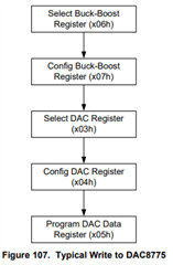
WRITE 0x06 0x01       // Select Buck boost register
WRITE 0x07 0x01       // Config Buck boost register
WRITE 0x03 0x20       // Select DAC register
WRITE 0x04 0x800     // Config DAC register Vout 0-5V
WRITE 0x05 0xFFFF  // DAC data register output 5V(Full scale)

Where are the things that are going wrong?

Thanks in advance.

  • Hi Amit,

    Thanks for reaching out  and we will get back to you by Monday.

  • Amit,

    Are you using the EVM GUI to configure the device or are you writing your own programming? 

    There are two things that could be happening to prevent the output from coming out of the device. First, make sure the reference is enabled on the EVM by setting bit 4 of the Reset Config Register (x02). This will enable the reference for the DACs. Without the reference, the DAC has no reference and the output voltage will remain close to 0V. Second make sure the DAC output is enable for the DAC channel. This would be OTEN which is bit 12 of the the Configuration DAC register (0x04).

    Note that the EVM GUI is rather helpful in showing the configuration of the device. Even if it doesn't specifically show the register settings, it's a convenient way to see the different options in the device configuration. 

    Joseph Wu 

  • Thanks Joseph.

    Can you please guide me through the register settings for setting up the DAC8775 in 4-20mA mode? 

    Can we use the GUI tool and send the SPI commands(register settings) to verify the settings?

    Thanks in advance

  • Amit,


    From your earlier post, you have most of what you need to set the DAC device for operation. As I mentioned, I think you probably only needed the reference and the DAC channel enable. I think the basic flow of programming the device would be similar to Figure 107 in the datasheet (shown below).

    However, I would probably use a sequence like the following:

    Reset
    Enable Reference
    Configure/Enable buck-boost for each channel
    Set Mode to 4 to 20mA for each channel
    Set DAC data registers
    Enable each channel.

    For the GUI, it's not a great way to see the digital commands, but it can be done. Each of the buttons or tabs do refer to some SPI command that is sent to the device, so you can at least see what needs to be set to configure the device the way that you want it. Even though there isn't a full register map that is shown for the device, you can do individual reads and writes to the device. In the EVM GUI, you can see the Block Diagram and Simple I/O tabs in the upper left hand corner of the GUI. The Simple I/O tab can be used to read or write to individual device registers.

    If you have an oscilloscope or logic analyzer you can look at the digital communications going to the device. Again, you can set the configuration of the device in the GUI and then see what is communicated to the device.


    Joseph Wu