This thread has been locked.

If you have a related question, please click the "Ask a related question" button in the top right corner. The newly created question will be automatically linked to this question.

ADS1282-HT: Reading and Writing the Registers

Part Number: ADS1282-HT
Other Parts Discussed in Thread: ADS1282, ADS1283

Hello,

I am able to write and read the ADS1282 registers, except the register 0x0a (FSC2). I suppose, I can write/change this register because the ADC output is changing but anytime when I read it (0x0a), the returned value is 0x0a. I can write and read FSC0 (0x08) and FSC1 (0x09) without problems.

What am I missing here?

Regards,

Marius Raducanu 

  • Hello Marius,

    There's nothing different between any of the calibration registers. I do find it strange that the returned value is 0x0a, the reset value is 0x40. Could you reset it and read it back to see if you get the reset value? 

    Best,

    -Cole

  • Hello Cole,

    Yes, it is strange that the returned value is 0xa, the same as the register number. First, I suspected that I swapped in the firmware the returned value with the register number but it wasn't the case. Writing the register, affects the output according to the documentation (change the gain) but the reading is anytime the same, 0x0a. For instance, the first register 0x00, read/returns 0x20 (ID) as it should. As I said, I can write/read all the other registers without problems. I am building a second system and I will test it to see if I get the same problem.

    I am resetting the ADC with the RESET pin in the system anytime I use the SPI - I am using this as a replacement for the Chip Select, having a DAC (AD5600) on the same SPI. 

    Another strange problem is setting the gain in CONFIG1 (0x02). I am able to write/read the register/gain PGA[2:0] without problems. After I set the ADC input to zero, changing the gain from 1 up to 8 increases normally the ADC output "noise"/fluctuation. A further increase in the gain (16 to 64) changes ALSO the offset with more than 4000 ADC units - the Offset registers are not changed, only the ADC output. Do you have an explanation for this?

    Regards,

    Marius Raducanu


  • Hello Marius,

    Looks like there's a couple of things I want to confirm with you:

    I am resetting the ADC with the RESET pin in the system anytime I use the SPI: 

    Just note, this resets your register settings and restarts the conversion process which means you have to wait for for the data to settle before looking at measurements again. This "works" but is not recommended.

    Note, you can reset the SPI interface on the ADS1282 if SCLK is held low for 64 DRDY cycles, data transfer or commands in progress terminate and the SPI interface resets. I hope the resets are not contributing to the behavior.

    I am using this as a replacement for the Chip Select

    There's a couple things you can do to fix this, besides just resetting the device.

    • Use separate SPI peripherals for each ADC (if the MCU or FPGA can support this).
      OR
    • MUX the SCLK signal so that you only communicate with one device at a time. Here is an example schematic:

    4505.ADS1281-2 Shared SPI Schematic (1).pdf

    • Alternatively, if you're not set on the ADS1282, you could check out the ADS1283. It has improved SNR and has lower power consumption.

    After I set the ADC input to zero, changing the gain from 1 up to 8 increases normally the ADC output "noise"/fluctuation. A further increase in the gain (16 to 64) changes ALSO the offset with more than 4000 ADC units - the Offset registers are not changed, only the ADC output. Do you have an explanation for this?

    In general, gain and offset are independent and uncorrelated errors so this is unexpected.

    As a result, I suggest you drill down into your test set up. Sometimes, I see users forgetting to apply the common mode voltage after the shorting the inputs (as opposed to just setting them to GND, which may or may not be the common mode voltage, depending on the supplies. Though it is a bit easier by shorting the inputs internally). Also, to eliminate noise in the measurement, its best to run the calibration multiple times and average the result to have the offset converge the final value. 

    Otherwise, yeah, this is unexpected. Common specs like SNR and THD degrade with the increased gains, but 4000 codes seems like a lot.

    We can grab the FFT to see if there's anything else that doesn't look right. If you can, grab some time domain data and throw it in the Analog Engineer's calculator: https://www.ti.com/tool/ANALOG-ENGINEER-CALC you can get an FFT (using the load ADC data button, and formatting your data as described after clicking the Help button). This blog should help you get some of the other things like LSB size if you're not familiar: https://e2e.ti.com/blogs_/archives/b/precisionhub/posts/it-s-in-the-math-how-to-convert-adc-code-to-a-voltage-part-1 

    Best,

    -Cole

  • Hello Cole,

    "Note, you can reset the SPI interface on the ADS1282 if SCLK is held low for 64 DRDY cycles, data transfer or commands in progress terminate and the SPI interface resets. I hope the resets are not contributing to the behavior."

    No, this is not the problem. I have two DACs on the same SPI that I use to set a reference for an instrumentation amplifier (INA128U) to balance a strain bridge. I do this only one time when the system is powered ON. This is a prototype board, in the final version I will use different SPIs - I have discussed this with you in a different question/thread.

    At the ADC inputs I have two strain bridges, each simulated by four 350 Ohm resistors and powered by 5V. 

    I am using ADS1282 because is 175C rated. 

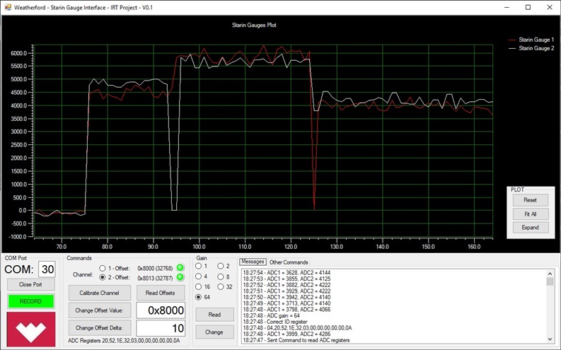
    Below is a screenshot of the application I've developed where I plotted the ADC outputs every second. The plot starts with values close to zero and then I change the gain from 1 to 64. When I change the gain to 16, the plot jumps more than 4000 units (first step in plot) on both channels. At gain 32 jumps another 1000 units (second step in plot). When the gain is changed to 64 the output decreases to ~4000 (last step in plot) .

    The application displays also the registers: 20,52,1E,32,03,00,00,00,00,00,0A

    Regards,

    Marius Raducanu

  • Hey Marius,

    I thought I recognized your name! Yeah, not a lot that can be done about the temp rating.

    Large jumps in codes when changing the gain:

    As for this, I'm having some trouble knowing the x-axis in the time domain (it kind of just looks like the sample number, not sure if it is context of your sampling rate). But if this is relatively "quick" in the time domain then the discontinuity (i.e. 4k code jump) is more expected.

    When we change gains, we are actually switching resistors in and out of the feedback path of PGA, and purging what's in the digital filter. What I mean by this, is that we expect the filter to go through the process of "re-settling". To be more detailed, you understand that when you have a step input into the digital filter, you expect to wait some time for the output settle. Between the timing of breaking the feedback loop of the PGA to add in new resistors, and resetting the data that's going the filter stage to "zero", then we get the same sort of discontinuity behavior. 

    Don't get me wrong, the timing is a bit "hand-wavy" but it is expected. When you said this earlier, I thought the new gain setting was converging to somewhere 4k codes later. So we just recommended, when you change the gain, add a routine in software that requires the output to settle after changing the gain (just like the routine you should have when you first turn the device on). Does that make sense?  

    Different settling points for different gains.

    As for the changes in convergence points for each of the gains, this is expected as well, for two important reasons. The first is that the offset is always input referred to the PGA. So, if you have a fixed offset, changing the gain will change the output after the PGA (and the codes seen at the output). This is more op amp knowledge than ADC knowledge and there's a good TIPL video on it if you want me to send it.

    The lesser known fact is that the input paths are physically different for gains 1 through 16, 32, and 64. You can always infer this by looking at the spec tables. I pasted THD below (it looks blurry on my screen, clicking on it will increase quality somehow). So, I know I said gain and offset are uncorrelated, but in context of error analysis, its like we're using a different uncorrelated op amp with a different offset and gain error (for the record, we don't use different op amps for the different gain stages, I'm illustrating a point in context of error analysis). 

    At the end of the day, this is still DC error that can be calibrated out. And we recommend you do this whenever you change the PGA setting, as shown in the datasheet.

    Hope this helps.

    Best,

    -Cole

  • Hi Cole,

     "I'm having some trouble knowing the x-axis in the time domain ..."

    The ADC channels are sampled with 2x50Hz averaged and displayed every second.

    "So we just recommended, when you change the gain, add a routine in software that requires the output to settle after changing the gain (just like the routine you should have when you first turn the device on). Does that make sense? "

    I can fix it (make the offset 0 after changing the gain - I developed an automatic offset calibration using a DAC) but I wanted to confirm if the 4000 jump is normal/expected?

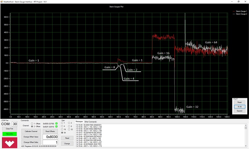
    Also, the jump is not so big when changing gains to 2 (10ADC), 4 (20ADC) or 8 (40ADC) but evident on the gains 16, 32 and 64.

    Below is another screenshot - changing gains from 1 to 64. This time, the Offsets are smaller, I don't know why.

    Still, I don't now why the value of the register 0x0a (FSC2) is 0x0a when I read it.

    Regards,

    Marius Raducanu

  • Hello Marius,

    This is helpful. Well, I would say this correlates pretty well with my previous explanation, though I am surprised to see that the offset doesn't seem to be jumping the same amount. So, in general, I don't have concerns here.

    Still, I don't now why the value of the register 0x0a (FSC2) is 0x0a when I read it.

    This is still a problem, but root cause points closest to your read routine. If writing changes the behavior the device (which means writing is fine) and reading yields 0xA0 no matter if you just reset or if you just finishing writing to that register, then the read routine is at fault. Don't get me wrong, there's no reason for reads to work for every other register but this specific register. So, we have to verify the basic assumptions before moving on.

    As such, we need to verify that the code is executing the right command. Can you use a logic anaylzer or oscilloscope to verify the right command is being sent?

    Alternatively, if you have the second set up running, you can see verify it isn't a one board problem. I'll see if I can grab one of my EVMs and reproduce the issue. 

    Best,

    -Cole

  • Hello Cole,

    "As such, we need to verify that the code is executing the right command. Can you use a logic anaylzer or oscilloscope to verify the right command is being sent?"

    I am sure that I use/send the correct command (RREG) because I read all 11 registers with one command. The other 10 are read correctly.

     void ADS1282_Read_Registers_Data(unsigned char reg, unsigned char nrofreg, unsigned char * regdata);

    I have developed and tested successful functions to read and then write register(s) - for instance for changing the gain or the channel.

    "Alternatively, if you have the second set up running, you can see verify it isn't a one board problem."

    I will do this today and confirm.

    Regards,

    Marius Raducanu

  • Hey Marius,

    Ahhh, yes, designating the number of registers to be read is really hard to mess up. Good to know you don't read the registers individually. This makes me think this might shift it into device bug category but I'll have to try it on my side too. This will take a couple of days for me, expect an update somewhere in the middle of next week. 

    Thanks,

    -Cole

  • Hi Cole,

    Thanks for your help.

    Reading this particular register (FSC2) is not critical (the other works to be read/write). I can write it and observe the change in the gain accordingly - so the reading doesn't work but the writing works. Other registers are indeed critical to read - for instance, to change the gain or the MUX (channel), I have to CORRECTLY read the register first, change the corresponding bits and then write it back.

    I understand the effect of changing the ADC internal switches to set the gain but from the usage point of view, it is very inconvenient to have the offset change with changing the gain: 10-20 ADC units for gain 2, 20-40 ADC units for gain 4, 40-80 ADC units for gain 8, jump of ~4500 units for gains 16, 32 and 64. 

    Regards,

    Marius

  • Hi Cole,

    I was able to test the second system and I got the same reading of the FSC2 register, constant (0x0a).

    The offsets are much smaller than the offset of the first system - how I expected to be, increasing proportional with the gain and up to maximum 200 ADC units for gain 64 (not a ~4000 ADC units jump). The two system are identical, the only difference is the ADS1282 - maybe the first ADC has problems.

    Regards,

    Marius

  • Hi Cole,

    I found my mistake in reading the registers:

    ADS1282_Read_Registers_Data(0, 11, receive_spi);
    serial_out_cstr("04,");
    for(i=0;i<10;i++)
    {
    serial_out_Hex(receive_spi[i]);serial_out_char(',');
    }
    serial_out_Hex(10); OutCRLF();

    Instead of sending to the serial the register 10, I send 10.

    Regards,

    Marius 

  • Hello Marius,

    I found my mistake in reading the registers

    Nice find! Let me know if the issue is resolved.

     it is very inconvenient to have the offset change with changing the gain

    Thanks for the feedback. This is an interesting one because its clear that the design team expects the user to recalibrate after changing the gain. With this given, I wouldn't really care about how much the offset would change because its going to be calibrated out anyways. The fact that I need to recalibrate at all would be inconvenient but I don't have the system knowledge to know what I'm losing by having to calibrate frequently. I do know that making extremely low offset devices (without calibration) can be more expensive because of tightening up some of the tolerances in the design process, so there is a clear tradeoff there (without a marginal benefit because I can get similar performance by just taking the time to calibrate). 

    If you want to expand on how this affects the system and its workflow, feel free to elaborate. If not, I'll pass it along to the team and see how the next device can be designed even better. 

    Thanks,

    -Cole

  • Hello Cole,

    Now, I have two identical systems: one of them has acceptable levels of offset when the gain is changed, one has big jumps in offset when the gain is changed. The bigger problem I see now, is that the offsets are not constant, they change anytime the gain is changed (in both systems) - for instance: set gain 16 -> set gain 32 -> set gain 16 - when returning to gain 16 the offset is different. I am still testing these systems, let you know the results and confirm this based on more tests.

    I want to develop an Automated Gain Control - set the gain, function of the input signal. If the offset changes with the gain this cannot be done - or at least cannot be done easy - I haven't tried to use MUX to use the internal 400 Ohm resistors for measuring offsets and I don't know if they remain constant.

    At this time, the system I am designing can work with ADS1282 - having a solution or clarifying the changing offsets will improve the system even more.  

    Regards,

    Marius Raducanu 

  • Hey Marius,

    Thanks for the context. I usually use the internal 400 ohm resistors for measuring the offset, its what we used to generate some of the specifications in our datasheet. I recommend evaluating it. This is the path I would take to a develop a Automated Gain Control while still calibrating for offset after each gain selection. 

    In the meantime I'll see if I can get any general info about the tolerance of those 400 ohm resistors because I don't think we have that kind of info in the datasheet.

    Best,

    -Cole

  • Hey Maruis,

    So, the big sources of error for offset will be the input bias current to the PGA (V_out_IB = I_Bias*R*Gain) and the resistor tolerance (in addition to voltage offset, which is in the datasheet).

    We have input bias current for you below in the graph. In short, 10s of pico-amps CHOP = off, and 1s of nano-amps when CHOP is on. Also note the 1000% increase at 210C as told by the datasheet spec.

    The resistors have a +/-15% tolerance, the temp drift tolerance is pretty negligible (1s of ppm).

    Best,

    -Cole

  • Hi Cole,

    Thanks for the info.

    As I said, I have two supposed identical boards. One has big offsets when the gain is change and the other has acceptable (very good) offsets when the gain is changed.

    I suppose, there is a problem with the first board. I will investigate and report back.

    Now, I am very satisfied how the ADS1282 works. I will build 10 prototypes systems (175C) based on this ADC. The price is high but is the only option on the market at this time.

    Thanks,

    Marius Raducanu

  • Great work Marius. Feel free to click the Ask Related Question at the top, when the time comes. It'll help prevent the thread from getting too long.

    Yeah, I definitely acknowledge what's going with the market this at this time. Hope the build on the other 10 boards is smooth. Best of luck.

    Best,

    -Cole