Other Parts Discussed in Thread: LM5166
Hi,
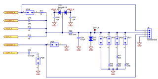
Can you please review the attached schematics once.
Thanks in advance.
Regards,
Amit Jain2727.SCH_DAC8775.pdf
This thread has been locked.
If you have a related question, please click the "Ask a related question" button in the top right corner. The newly created question will be automatically linked to this question.
Amit,
First, along with the datasheet, there are a couple of other documents you can use as templates for your schematic. First, the EVM can be used as a template for a schematic. The EVM schematic should operate to the specifications shown in the datasheet. Additionally, you can get an EVM and test it before you design your own schematic. Second, there are a couple of TI designs that use the DAC8775 in the schematic. The TI Designs will each have a design guide and a schematic.
The EVM user's guide can be found here:
https://www.ti.com/lit/pdf/sbau248
The TI designs featuring the DAC8775 can be found here:
https://www.ti.com/tool/TIPD216
https://www.ti.com/tool/TIPD215
Reviewing your schematic, it is similar to the that in the EVM. There are a couple of things that I wanted to point out though. The recommended value for the inductor is 100uH but it must have at least a 500mA peak inductor current. Additionally, you should add some diodes that prevent the output from going beyond the VPOS_IN_A and the VNEG_IN_A supplies of the buck-boost converter. In the EVM it looks like this:
There are a set of BAV99-7-F diodes between the IOUT/VOUT and the ferrite bead.
I did take a quick look at the LM5166 in the schematic, but I don't really have any experience with the device. I think it would be best to post that in the DC-DC converter forum. The values seem correct for an output of exactly 12V. Also, the ISO7641 isolation looks correct, but I don't have much experience with that as well.
If you have any other questions about the DAC8775, please let me know and post back.
Joseph Wu