This thread has been locked.

If you have a related question, please click the "Ask a related question" button in the top right corner. The newly created question will be automatically linked to this question.

ADC + Wireless transfer

Other Parts Discussed in Thread: ADS8586S

Hi Team,

For my project I need to take reading from 6 current transformers installed at 6 different locations at the same time. For this simultaneous sampling should be required right? If so can you suggest me a chip which got 6 ADC at least in built in it, because space is a constrain for my project. (little the board better for my work)

I need to take the sampled values from ADC to mobile or laptop through WIFI. How can I implement that ? Is there is a single board that I can choose so that both of these work can be done using a single board? or should I go for separate boards for ADC and WIFI with some communication like SPI between them ?

Please help me out. I am quite new to the embedded design area but I must say It is interesting Slight smile

Best Regards,

Vineeth 

  • Hi Vineeth,

    What sort of speed/resolution are you looking for in the ADC?

  • Hi Tom,

    I am looking at 1000 samples per cycle for a 50 Hz waveform so it will be 50000 samples per second. For resolution, I can go for 12 bit or 16. And will there be any significant difference in terms of performance and accuracy between SAR and Delta sigma ADCs?

  • Hi Vineeth,

    Take a look at the ADS8586, it's a 6-channel Simultaneous Sampling SAR converter that customers often use for current transformer measurements.  It allows for wide ranges of inputs on a +5V analog supply.

    https://www.ti.com/product/ADS8586S

  • Hi Collin,

    Thank you for your suggestion. I will look into it and will let you know my thoughts on it.

    Regards,

    Vineeth

  • Hi Collin,

    I read the datasheet of ADS8586 and I have one question. Till now I was told that I am not supposed to give ADC negative inputs. Since the ADC measure only from 0V to Vref V. But for this device ADS8586 it is said that it is possible to give +/- 5 and 10 V inputs. Am I reading this correct?

    I am not getting the idea about bipolar inputs can you please explain or can suggest me a read? My plan was to capture signal from CT then level shift it before feeding it to ADC

    Regards,

    Vineeth

  • Hi Vineeth,

    Your understanding of most common ADC architectures is correct.  This ADC is different than most as it has an analog-front-end (AFE) in front of the ADC.  This allows the device to attenuate incoming analog signals and from a 0-5V supply the ADC inputs can accept +/-10V directly.  

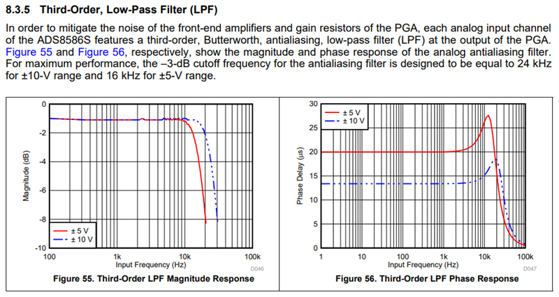
    Some effects of this type of ADC architecture is the 1MΩ input impedance and the ~15kHz AFE bandwidth such that the noise meets the 16-bit required resolution.  So, this product has a analog bandwidth that is lower than the Nyquist bandwidth set by the sampling rates.  It should work just fine for 50/60/100/120Hz type applications.

  • Hi Collin,

    I am very sorry I accidentally reported the reply as abusive, I was actually searching for the "QUOTE" option. Very sorry is there is anything that I can do to undo this?

     Regards,

    Vineeth 

  • Hi Collin,

    So, this product has a analog bandwidth that is lower than the Nyquist bandwidth set by the sampling rates. 

    I didn't quite get this point. If I am sampling at a rate of 50000 samples per second this ADC will just work fine right? And the bandwidth you said 15kHz is applicable for input signals like anything more than 15kHz will get attenuated at AFE is that correct?

    Regards,

    Vineeth 

  • Hi Vineeth,

    No problem, the moderators will take care of the reply.  Thanks for posting back on the accidental submission. 

    Yes, this ADC supports sampling rates up to 250kSPS and all channels are sampled at that rate.  Slower sampling rates, like 50kSPS, are fine as well.  

    The point was that with a traditional SAR ADC without an AFE, the Nyquist bandwidth with a 50kSPS sampling rate would be 25kSPS.  In the ADS8586S device, the AFE sets the analog bandwidth as spec'ed as shown in the datasheet below:


  • Hi Collin,

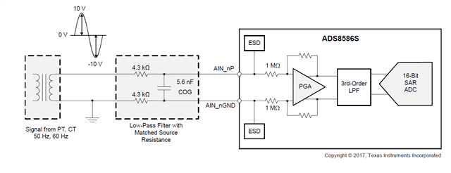
    Thank you for your response. Now I get it. One more thing, in application note it is shown the ADS8586 is used for CT and PT measurements. 

    We have to give burden resistor between the secondary terminals right. Or can we connect it directly as shown in the figure?

    Also for using serial data transfer scheme how the clock can be generated, since it doesn't having SPI module? 

    Do we have any sample codes on serial data transfer (preferable bitwise code) ? 

    Regards,

    Vineeth

  • Hi Vineeth,

    Yes, this product is meant for multi-channel Grid applications where common inputs are CT/PT/Shunt, Rogowski Coil, etc.

    Check w/ the datasheet for the CT/PT you're using to determine the proper burden resistance and include it.  It may have been left of this diagram for simplicity.

  • Hi Collin,

    Thank you for your response. I think I can continue from here. Thanks for your support, Means a lot.

    Regards,

    Vineeth