This thread has been locked.

If you have a related question, please click the "Ask a related question" button in the top right corner. The newly created question will be automatically linked to this question.

ADS127L01: 24bit resolution?

Part Number: ADS127L01
Other Parts Discussed in Thread: ADS1220, ADS1256, ADS127L11

Hello

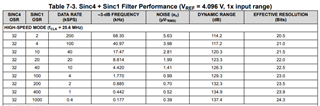
I have a general question ADS127L01 24 bit ADC. The maximum ENOB from the datasheet is only 21.83 bits at 2000 sps and max OSR of 2048.

Similarly I see other 24bit ADCs also but after looking through the datasheet their ENOB is only around 20-21 bits (ADS1220 advertised as 24 bit but 20.08 bit ENOB at 20sps).

There are some like the ADS1256 that truly achieve the 24bit ENOB with low data rates. 

So wondering why ADS127L01 and ADS1220 are advertised as a 24 bit ADC. I must be missing something in their implementation or interpreting the datasheet incorrectly? I am hoping someone could help me with my understanding. 

Thanks

Raghu

  • Hello Raghu,

    ADC manufacturer's classify an ADC resolution by the number of bits that you can read from the device.  ENOB is based on the internal noise of the ADC and the resolution.  Different ADCs have different internal noise levels, which is why the ENOB for a given data rate is different for various ADCs.

    Even though the ENOB is less than 24b, you can always use additional digital filtering on the collected data to increase the ENOB of the measurement.  As an example, the ADS127L01 is specified with ENOB(or effective resolution) of 21.83b (1.34uVrms noise) in VLP mode and OSR=2048.  If you further filter this data in the host processer, you can increase the ENOB.  Using a simple average filter and averaging 16 readings, the noise will reduce by a factor of 4, Vnoise=1.34uVrms/sqrt(16)=0.335uVrms.  This will result in an ENOB(effective resolution) of 23.83b.

    You may want to take a look at the TI Precision Labs -ADCs.  There is a lot of good information in these presentations that discusses noise in both SAR and Delta-Sigma ADC topologies.  Specifically, section 4, Analog-to-digital convert (ADC) drive topologies has some good information about this topic.

    Regards,
    Keith Nicholas
    Precision ADC Applications

  • HI Keith

    "ADC manufacturer's classify an ADC resolution by the number of bits that you can read from the device."

    I was not aware of this. I always assumed it would be by the ENOB because thats the usable bits coming out of the ADC anyways. I guess I was thinking about the ADC as a stand alone with no external post processing. Your reply makes a lot of sense to me now. If you can read 24 bits, then external post processing would indeed reduce the noise floor. 

    But I do have one doubt about the amount by which it will reduce the noise. Reducing noise by averaging (noise decreasing by root of the number of readings averaged) only works when the noise is truly random in nature. But since the noise profile coming out of a sigma delta ADC is noise shaped by its SINC digital filter, can we say with confidence that this truly is random and will decrease by the root of the number of readings averaged? 

    Thanks

    Raghu

  • Hi Raghu,

    With delta-sigma ADC's, there are usually multiple filter options, so depending on the specific filter used, the effective resolution will change.

    You are correct, the amount of noise reduced on the digitally filtered data will depend on the filter response.  However, 1/sqrt(OSR) is a good approximation.  The only way I know to get an exact number is to mathematically combine the filter response of both filters (the internal digital filter and the external filter response resulting from averaging in this example), and then integrate the overall response. 

    Here is an example from the new ADS127L11 delta-sigma that has an option for a SINC4+SINC1 filter.  For the lower SINC1 OSR (number of averaged results from the SINC4), the reduction in noise is predicted by 1/sqrt(OSR), but for higher levels, the reduction is not as great, but the simple equation predicts the total noise for OSR up to 100 to within 24%.

    SINC4 filter, OSR32, Noise=7.96uVrms

    SINC4, OSR32 plus SINC1, OSR2, Noise=7.96uVrms/sqrt(2)=5.63uVrms, actual noise 5.63uVrms, 0% error

    SINC4, OSR32 plus SINC1, OSR100, Noise=7.96uVrms/sqrt(100)=0.796uVrms, actual noise 0.99uVrms, 24% error

    Regarding the use of the term ENOB in TI's older delta-sigma datasheets, the resolution term that we are specifying is effective resolution, not ENOB.  All of the above examples are effective resolution, which is a DC specification based on the internal noise of the ADC when the inputs are shorted.  This can be calculated using the following formula:

    Effective Resolution (bits) = 3.32*log10(FSR/noise)

    FSR=full scale input range, for the ADS127L11 in 1x range, this is 2*Vref.

    ENOB is based on AC performance, where a low noise and low distortion sinewave (1kHz is common) is sampled, run through an FFT algorithm, and the SINAD (ratio of full-scale signal-to-noise and distortion) are calculated and used in the following formula:

    ENOB=(SINAD(dB)-1.76dB)/6.02

    ENOB will always be less than effective resolution, since the FSR is based on the maximum RMS level of a sinewave, or FSR/[2*sqrt(2)]

    If the ADC distortion is very low and the noise is dominated by thermal noise, then you can estimate ENOB=Effective Resolution - 1.8b.

    On new device datasheets, we are using the term effective resolution if it is based on input shorted noise.  If ENOB is used, then it is based on the above equation using an input sinewave.

    I hope this helps!

    Regards,
    Keith

  • Hi Keith 

    Thank you fr your reply and such a detailed explanation. 

    One question about the table that shows sinc4 OSR in the first column and sinc1 OSR in the second. Is that data getting averaged, sent to a sinc4 filter and then again getting average and then sent to a sin1 filter to get the effective resolution higher. If so, that pretty cool and I do see your point of approximation. 24% error is not too shabby. 

    Following up from this table, I now am wondering that if we do post process the data coming out of ADS127L01 by averaging to bring the effective resolution up, do you see the need to run it through an FIR sinc filter again? I am questioning on why the ADS127L11 used a sinc1 after the second OSR?

    Whats the advantage of breaking up the sinc filtering in stages?

    Your explanation on ENOB vs effective resolution also definitely made sense. 

    Thanks

    Raghu

  • Hi Raghu,

    Just to be clear, the SINC1 filter is equivalent to an averaging filter.  So in the above example, the SINC4 output is averaged by the SINC1, where OSR is the number of samples from the SINC4 output that are further averaged together.

    In the above table, the SINC4 filter is fixed at OSR32; it uses 32 modulator input samples to generate an output that has a data rate (internal to the ADC) of 400ksps.  The SINC1 takes the SINC4 output and further averages these values where OSR is equal to the number of output samples from the SINC4 that are averaged together.  If you take the output of the ADS127L01 low-latency filter and further average it in your host processor, you can expect to get further reduction in noise, which will result in higher effective resolution (and ENOB).

    The advantage of breaking the filters up is a tradeoff between noise and latency.  Using the ADS127L11 again as an example, setting the SINC4 to an OSR of 128 results in an output data rate of 100ksps (high-speed mode, Fclk=25.6MHz), a noise of 3.90uVrms and a latency of 40.63usec (total time for the digital filter to settle).  Using the SINC4+SINC1 option, where the SINC4 OSR is fixed at 32 and the SINC1 is set to an OSR of 4, you will get the same 100ksps data rate, but the noise has increased to 3.98uVrms and the latency is now 18.13usec.

    Regards,
    Keith

  • Hi Keith

    Thank you so much for pointing this out. I had to do some thinking after reading your last message and it made total sense to me. Digital averaging/moving average over a set of samples ( rectangular window in time domain) is sinc in the frequency domain. Over the weekend, I was quickly able to create a sinc filter in python and use it to average the samples coming out of my the ADC to drop my noise floor and further improve the effective resolution. Also the flexibility of using the sinc filter to eliminate 50Hz line frequency was quite satisfying to see. 
    Again, thank for taking the time to reply to my questions. I definitely learn a lot when I interact with e2e. 

    Thanks

    Raghu