


Other Parts Discussed in Thread: ADS1298
Hello TI Community,
I have been playing around with ADS1298 for ECG and EMG acquisition.
I have made a custom PCB that interfaces ADS1298 and Teensy 3.2 (using the Arduino interface).
I have followed the following flowchart given in the ADS1298 datasheet.
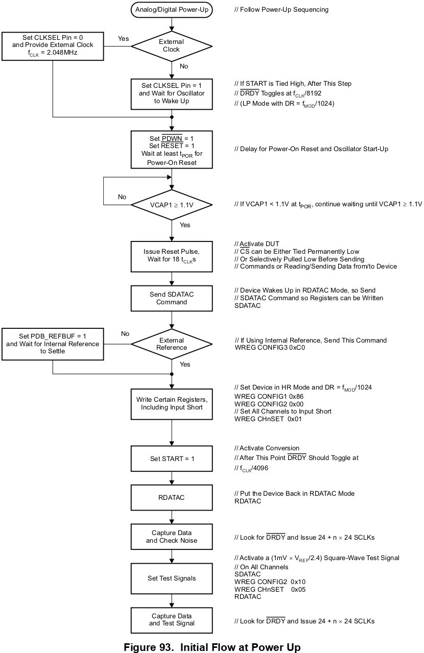
The settings that I have chosen are as follows:
- LP mode
- DR = 250sps
- I have attached the registers settings below:
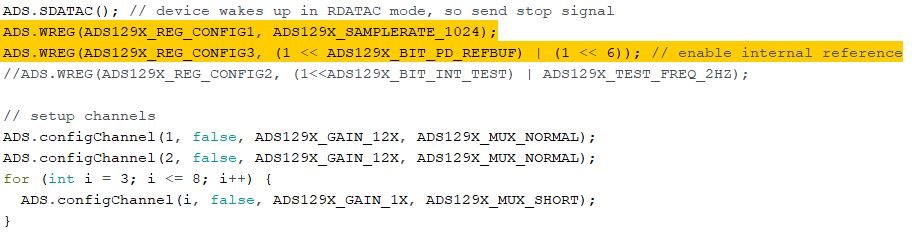
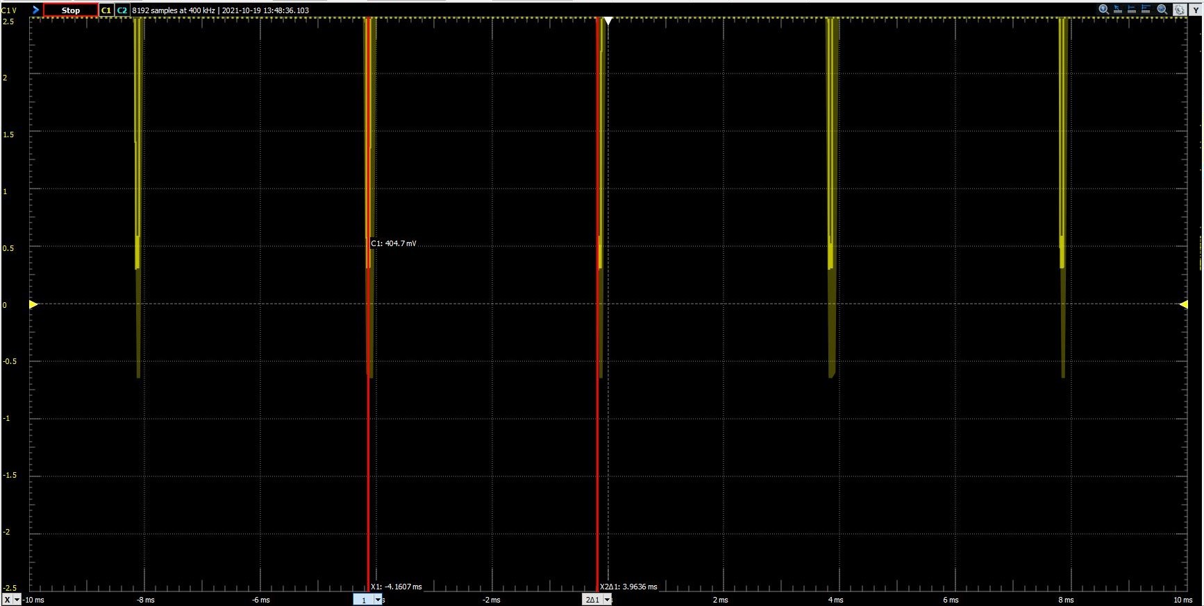
I have also checked the DRDY signal, again attached below:
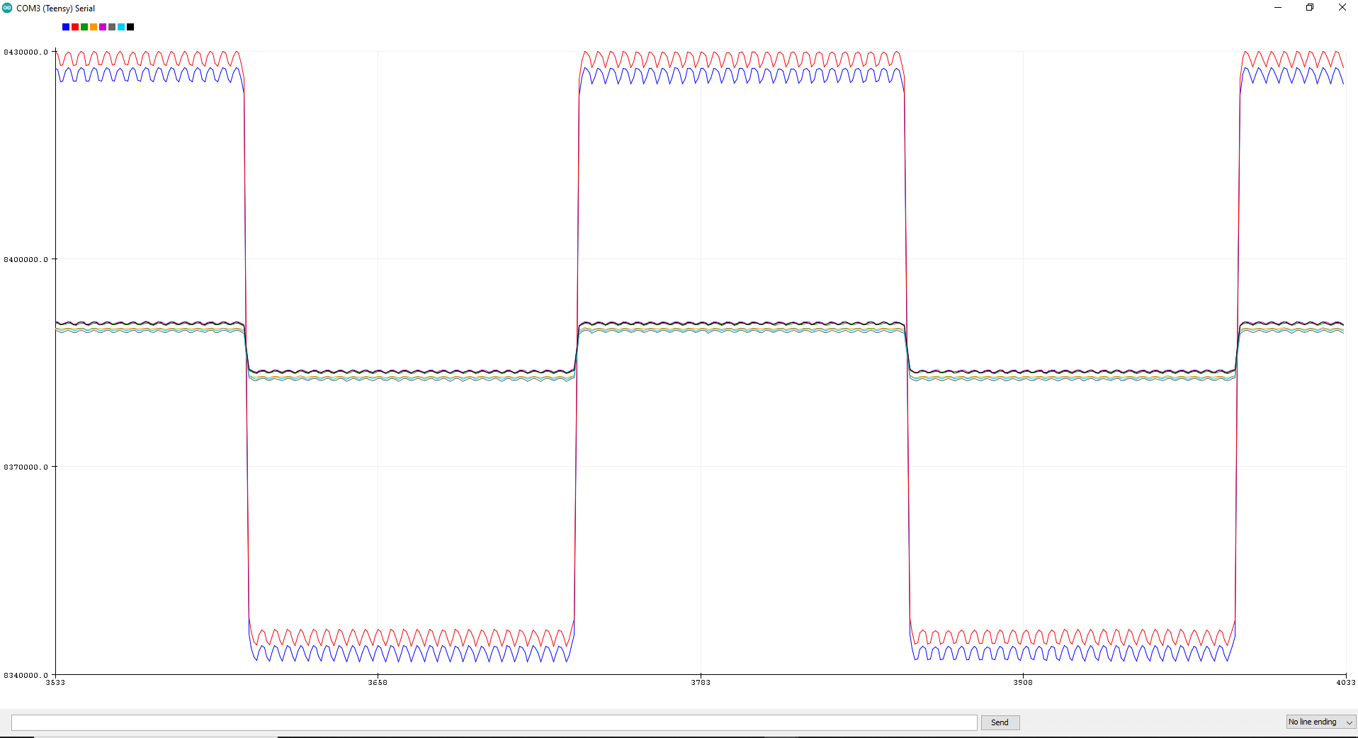
Also, I have tested the IC using an internal test signal (Channel 1 and 2 are kept at 12X gain whereas the Rest of the channels 3 to 8 are kept at a 1X gain):
Also, I checked the internal voltage nodes as you have available on my device:
- VREF = VREFP – VREFN = (0- (-2.5V)) = 2.5V
- VCAP1 = AVSS + 1.2 V = -2.5 + 1.2 = -1.3V
- VCAP2 = (AVDD + AVSS) / 2 = (2.5-2.5) / 2 = 0V
- VCAP3 = AVDD + 1.9 V = 2.5 + 1.9 = 4.4V
- VCAP4 = (VREFP + VREFN) / 2 = (0 - 2.5)/ 2 = -1.25V
- The above internal voltage node values are calculated and when I probe these nodes I get the same values.
SO the issue I am facing is as follows:
- I have connected the electrode cables at IN1P and IN1N (And similarly for the rest of the inputs 2-8 channels) and placed these electrodes on my forearm in order to extract the differential signal (in EMG form). I am not getting the EMG burst signal when I flex my muscle. What could be the issue?
- Can you check my register configuration? The SPI is working since I am able to read back the register after writing them.
- What should be the configuration to set (Not necessarily optimum one but a rough idea) in order to acquire ECG and EMG signals?
- Also, I might have many follow-up questions too.
PS: DO not forward me another discussion thread
