This thread has been locked.

If you have a related question, please click the "Ask a related question" button in the top right corner. The newly created question will be automatically linked to this question.

DAC7750: 50mA current out default on power up

Part Number: DAC7750

Dear Team,

I am using DAC7750 with a PIC controller.

The problem i see is that, when i power up the default current i get out is approx 50mA without configuring anything.

I could not establish communication as well. I always read a 0xFF or 0x00 sometimes rarely 0xFD from the control register after putting in some data.

I can inspect the communication part next with a oscilloscope, but the current out of 50 mA really worries me without doing anything. (added a 150E load resistor on the outputs and got a 8.9V across it)

Is there something i did wrong or any chances on how this can happen ?. I tried pulling the CLR pin directly to GND as well referring to the other schematics in the forum.

I tried it out with my another proto board as well, but both resulted in the same behavior.

  • just another info that i messed to add

    1) I am testing the module with 12V, means AVDD is powered with 12V 

    2) ZD2, ZD3, D7, C11 are not mounted.

  • Surya,


    I think the first thing you should do is check all the physical connections to the device and make sure there isn't any problems with solder bridges and other wiring. Make sure that the correct voltages are at the pins and make sure the digital outputs from the microcontroller are going to the digital inputs of the device (and vice versa). Perhaps you can send us a copy of your layout and perhaps a photo of the board.

    Next, can you report all the register settings that you have sent to the device? I think one thing that might cause the output to be much higher is to have no resistor on the ISET-R pin and then accidentally set the device to use the external resistor. Post back with any of the communications that you have sent to the device.

    I don't think they are absolutely necessary, but you can also add some capacitors to CAP1 and CAP2. That would be something else to try.


    Joseph Wu

  • Thanks a lot Joseph for your reply with the hints.

    I will try to do these changes

    1) Check the ISET-R pin

    2) Try to add caps on cap 1,2

    In parallel i will send you the layout and the board images as well along with the default register settings.

    Surya

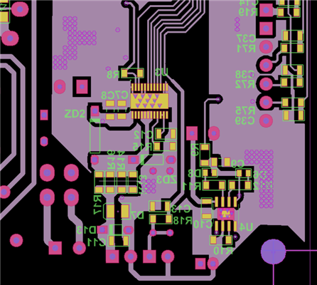
  • Attached the layout view of the DAC and a image of the prototype module. Maybe you see something strange that might help until we try the mentioned changes. 

    Thanks again for your quick support here

    .

  • Surya,

    I haven't studied this too in depth, but I don't see anything yet. Can you please send the register settings?

    Joseph Wu

  • /*
     * File:   DAC7750.c
     * Author: Evergreen
     *
     * Created on 15 October, 2021, 6:53 PM
     */
    
    
    #include "HeaderIncludes.h"
    
    #define ADDR_NOP         0x00
    #define ADDR_WRITEDAT    0x01
    #define ADDR_READDAT     0x02
    #define ADDR_WRITECNTRL  0x55
    #define ADDR_WRITERST    0x56
    #define ADDR_WRITECONF   0x57
    #define ADDR_WRITEGAINCAL    0x58
    #define ADDR_WRITEZEROCAL    0x59
    #define ADDR_WATCHDOG    0x95
    
    #define ADDR_READSTATUS     0x00
    #define ADDR_READDATA       0x01
    #define ADDR_READCNTRL      0x02
    #define ADDR_READCONFIG     0x0B
    #define ADDR_READGAINCAL    0x13
    #define ADDR_READZEROCAL    0x17
    
    
    #define DAC_LATCH   LATDbits.LATD3
    //#define DAC_CLR     LATDbits.LATD2
    
    volatile char Writedat[3] = { 0x00, 0x00, 0x00};
    void DAC7750_Write(char Operation, char* data);
    unsigned int DAC7750_Read(char ReadRegister);
    
    void DAC7750_Init()
    {
        /* Set latch and clr pins as outputs */
        TRISDbits.TRISD3= 0; 
        TRISDbits.TRISD2= 0; 
        
        DAC_LATCH = 0;
    
        __delay_ms(10);
      
        /* Reset DAC */
         Writedat[0] = 0x00; Writedat[1] = 0x01;
        DAC7750_Write(ADDR_WRITERST, &Writedat[0]);
        __delay_ms(10);
      
        //External current setting resistor disable, Output enable, Slew Rate disable, Daisy-chain disable, Output range = 4-20mA.
        Writedat[0] = 0x10; Writedat[1] = 0x05;
        DAC7750_Write(ADDR_WRITECNTRL,&Writedat[0]);
        __delay_ms(10);
    
        //calibration enable, HART interface disable, frame error checking disable, Watchdog timer disable
         Writedat[0] = 0x00; Writedat[1] = 0x20;
        DAC7750_Write(ADDR_WRITECONF,&Writedat[0]);
        __delay_ms(10);
    
        //gain register
         Writedat[0] = 0x80; Writedat[1] = 0x00;
        DAC7750_Write(ADDR_WRITEGAINCAL,&Writedat[0]);
        __delay_ms(10);
        
        //data register
         Writedat[0] = 0x00; Writedat[1] = 0x00;
        DAC7750_Write(ADDR_WRITEDAT,&Writedat[0]);
        __delay_ms(10);    
        
    }
    
    
    void DAC7750_Write(char Operation, char* data)
    {
        // Clock out 24 bit command
        spiWrite(Operation); // Address byte
        spiWrite(data[0]);
        spiWrite(data[1]);
        
        DAC_LATCH = 0; __delay_us(100); DAC_LATCH = 1; __delay_us(100); DAC_LATCH = 0; // Latch up data   
    }
    
    unsigned int DAC7750_Read(char ReadRegister)
    {
        static char Readback[4];
        
        // Clock out 24 bit command
        spiWrite(ADDR_READDAT); // Address byte
        spiWrite(ADDR_NOP);     // Bit 15-6 NOP
        spiWrite(ReadRegister); // Read register address
        
        DAC_LATCH = 0; __delay_us(100); DAC_LATCH = 1; __delay_us(100); DAC_LATCH = 0; // Latch up data
        spiWrite(ADDR_NOP); // Dummy 8 byte data
        Readback[0] = spiRead();
        spiWrite(ADDR_NOP); // Read out data from host
        Readback[1] = spiRead();
        spiWrite(ADDR_NOP); // Read out data from host
        Readback[2] = spiRead();    
       
        DAC_LATCH = 0; 
        __delay_us(100); 
        DAC_LATCH = 1; 
        __delay_us(100); // Latch up data
        DAC_LATCH = 0;
        
        return ((Readback[1]<<8)+Readback[2]); //Returns Result
        
    }
    
    
    void spiInit()
    {  
      TRISC3 = 0; // Clk as output
      TRISC5 = 0; // SDO as output
      TRISC4 = 1; // SDI as input
      SSPCON1 = 0b00100010; // Clk/64 + SPI Enable + Master mode
      SSPSTAT = 0b00000000; // Sample input at middle
    }
    
    static void spiReceiveWait()
    {
      while ( !SSPSTATbits.BF ); // Wait for Data Receipt complete
    }
    
    void spiWrite(char dat) //Write data to SPI bus
    {
      SSPBUF = dat;
    }
    
    char spiDataReady() //Check whether the data is ready to read
    {
      if(SSPSTATbits.BF)
        return 1;
      else
        return 0;
    }
    
    char spiRead()    // Read the received data
    {
      spiReceiveWait();      // Wait until all bits receive
      return(SSPBUF); // Read the received data from the buffer
    }


    Sure thanks again for your reply.

    Attached my code that i use to initialise the DAC. Using the "DAC7750_Init()" function during initialisation.

    Thanks

    Surya

  • Hi Surya,

    Can you check if the REFOUT pin is oscillating? The cap on the pin is very small (100pF), when we recommend more like 100nF.  It possible that this 100pF is causing some stability issue.  I recommend putting a 100nF cap and measuring again.

    Thanks,

    paul

  • Thanks a lot Paul. I placed a 220nF here and it worked. now the current out is limited within the specified range.

    Great Thanks again