This thread has been locked.

If you have a related question, please click the "Ask a related question" button in the top right corner. The newly created question will be automatically linked to this question.

ADS1235: Setup and Calibration

Part Number: ADS1235

Hello everyone
I'm developing a device that reads a load cell. Due to the characteristics of speed and precision I chose ADS1235. I developed a custom board and I'm currently at a stage where I can read data and edit registers. I don't have a lot of experience with ADC, but I am committed to learning. My question is about the best practices for performing the read value scaling and calibration adjustments.
My load cell is HBM pw15ahc3mr model. 5v excitation voltage / 2mV/V sensitivity
With this I conclude that the voltage range that the load cell will send to the ADC converter is about 20mV, correct?
Using the 128 gain I have the reading range on the ADS1235 of ±0.039 V, ±39mV, that is, the equipment will only use about 25% of the reading range of the ADS converter, is that it?

In theory, since the ADS1235 is a 24bit converter, the conversion range will be 0 - 16777215. That is, -0.039V = 0, +0.039V = 16777215. Is this idea correct?

I've read the manual several times, but I'm still not clear on how the calibration features work. Are there any more didactic material so I can learn better?

I have some standard weights to adjust the load cell readout and work with conversion calculations within the firmware. But first, at the level of the ADC converter, which settings and parameters should I pay attention to for its proper functioning?

Thanks

  • Hi Guilherme,

    If VEXC = 5 V and the sensitivity = 2mV/V, then you should expect an input signal of 10 mV with the maximum load applied. If you are only measuring compression (and not tension), then your input spans from 0V to 10mV within the -39mV to +39mV range. This is not necessarily a bad thing, as this might give you sufficient performance for your system depending on your target noise free counts. We have several resources available in our Precision Labs content that help address this issue, specifically check out the modules on ADC noise: https://training.ti.com/ti-precision-labs-adcs

    Do you have any specific questions about the calibration feature in the ADC? Or what did you not understand from the datasheet? I am not sure I can do a better job explaining in general the calibration features compared to what is in the datasheet. But if you have any specific questions I can help address those.

    -Bryan

  • Hi Bryan, thanks for your answer.

    I had a few advances today, but i have a doubt.

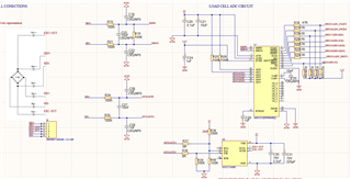
    Im reading the inputs 4 and 5 (differential mode). My schematics is following the datasheet.

    I'm trying to scale the digital read value to weight. But when i have nothing conected in the inputs, i read a value of 1179657. When i have the load cell connected i get 1188632 with 10.8mV between pin 4 and 5(pressing the load cell, this value decreases)

    With the loadcell unconected, the converted value shouldn't be 0?

  • Hi Guilherme,

    No, the load cell does not necessarily have a 0V output signal with no load. Ideally this should be true, but the load cell, ADC, input circuitry, etc., have some errors associated with them. You might need to set a zero point, or tare, the load cell. Right now the code you are getting is ~5mV, so there is some minor error under a no-load condition. What is the maximum weight you can apply to the load cell? If you apply this weight e.g. 10 kg, do you get a larger output voltage e.g. ~15mV?

    However, it might make more sense to bring up your system piece by piece. You have a lot of potential variables in your system (the AC excitation, the load cell, etc.), so it might make more sense to remove some of these and make sure the system works at each step along the way. So, remove the load cell and the AC excitation, and just make sure your system can accurately and precisely resolve a 1 V input with no gain, then a 10mV input with high gain (using a precision source). Then try the same thing with the AC excitation enabled. Once you add in the load cell, you can be sure the rest of the system is functioning properly. Perhaps you have already done these things, but if you have not, you should.

    Also, your schematic shows different ground symbols for analog and digital ground. Are these all connecting back to a solid ground plane, or do you have separate ground planes for digital and analog (the latter is not recommended)?

    -Bryan

  • Hi Bryan,

    I have all ground connected in a ground plane.


    I went a little further in testing today by enabling ac-bridge and doing several other tests. However I came across a possible problem related to the accuracy of the weight measurement. As I said earlier this project is for a quick drive system according to the weight reading, so I need speed and precision. However, I use a 10Kg max 2mV/V load cell. I need an accuracy of less than 1g in the measurement, however on my test i'm not achieving this accuracy, please check if it is correct.

    ADS1235 range reading with 128 gain =  78mV (+/- 39mV). ADC range 0 to 16777215
    So, there is a ratio of 215092.5 ADC units / mV (16777215/78)
    The voltage range of the load cell is 10mV (5V * 2mv/V)
    So I should have a range of 2150925 (10mV*215092.5 ADC units) when reading from 0 to 10Kg
    That is, 215 ADC units per gram

    However in the test I'm running I have the following

    gram / ADC units 
    0 / 1188631
    10 / 1188622
    20 / 1188613
    50 / 1188586
    100 / 1188541

    Could you help me understand why in practice I have the ratio of 0.9 ADC units per gram instead of 215 ?

    I'll put below some values ​​of the restrators that I changed:

    03h MODE1 - 01100001
    04h MODE2 - 1100000
    06h REF - 00001010
    10h PGA - 00000111
    11h INPMUX -01111000

    Thanks

  • Hi Guilherme,

    Please note that the ADS1235 uses a binary 2's complement coding scheme, and as such the full code range (2^24 codes) extends from -FS to +FS (decimal value -8,388,607 to +8,388,608). In your application, the full-scale range extends from -39mV to +39mV, though you are only using 0mV to 10mV of that range. This corresponds to the codes from 0 to 2,147,484, assuming an ideal ADC transfer function (no gain or offset error). So, ideally, when you place a 10kg weight on the load cell, you should see a decimal code of ~2,147,484. I just wanted to make sure there was no confusion per the statement that the "ADC range 0 to 16777215", which is not technically correct.

    However, I agree with your calculations that there should ideally be a change of ~215 codes per gram of weight. This implies that there is additional noise in the system such that you are not able to resolve these small changes. What data rate are you operating at? You did not provide the MODE0 register value in your last post.

    Also, have you confirmed that your board can read such small changes using a precision source, since the load cell can introduce a lot of variables into your system? It is best to check in advance if the system operates as intended before adding the sensor. At least then you can narrow down the possible causes. Right now it is not clear if it is the sensor, the board, or both that is adding noise. If you can verify that the PCB can accurately and precisely resolve your signals of interest using a precision source, this helps us identify where to start troubleshooting (and where not to).

    -Bryan

  • Hi Bryan,

    Thanks for your reply. i have  MODE0 and all other in default value:

    02h MODE0 - 00100100

    I'll try adding a potentiometer to test the board isolatedly. I will post the results here.

    Thank you

  • Thanks Guilherme, let us know what you discover

  • Hi Bryan,

    I did some more tests today and i think that the problem is on my PCB. 

    I measured the milivolts on the inputs and the correspondent values on the ADC

    0.1mV - 1179750 codes

    0.6mV - 1180102 codes

    Difference = 352 

    70.4 codes per 0.1mV

    But in theory i'm supposed to have 22075 per mV:

    8388608 / 38 *10

    I'm checking again the datasheet and my schematics, i did a lot of tests but i haven't found any solution so far. Do you suggest me any hardware or register value for testing?

    Thanks

  • Hi Guilherme,

    Your values seem to be way off. I measured the same values on my EVM just now (see below), and for 0.1mV I am getting a mean code of 38,597 (using G = 128, DR = 20 SPS, FIR filter on AIN0 and AIN1)

    How are you applying the input signal, and to which analog inputs? Are these single-ended inputs? And are these values from a precision source or are you using the load cell again? It might help if you could send a few pictures of your experimental setup.

  • Hi Bryan,

    I have the inputs conected on IN4 and IN5, in differencial mode. I have a custom board, but my schematics is following the EVM reference. I have tested with DC and AC excitation, both had similar behavior on output signal resolution. Testing with load cell or with a Wheatstone Bridge made up with resistor and potentiometer had similar results also.


    My parameters that are not default are:

    03h MODE1 - 01100001
    04h MODE2 - 1100000
    06h REF - 00001010
    10h PGA - 00000111
    11h INPMUX -01111000

  • Hi Guilherme,

    Have you tried bypassing the AC excitation hardware and just putting an input directly into the ADC via AIN4 and AIN5? Do you have a precision source you can use, as opposed to a load cell or a bridge? For my tests I used a Data Precision 8200, do you have any similar benchtop equipment that allows you to apply a known, clean input voltage to the ADC?

    At this point you are just trying to determine if your PCB functions correctly. If you use the internal reference, disable the PGA, and put a 1V signal into the inputs, do you get a 1V signal out? If you can start there that would be helpful to know that at least this works. If that works, then you would test the PGA functionality by enabling the PGA, setting the gain to some value >1, and seeing if your system converts this input correctly (keep in mind the PGA common-mode limitations). If you have questions about the PGA VCM range or code conversions, you can reference our Excel-based configuration calculator for the ADS1235: https://www.ti.com/lit/zip/sbar015

    If this works, then you try an external reference via REFP0 / REFN0, and so on, until you get to a point where the system stops performing correctly. Then you can start troubleshooting. But right now you have not established any baseline performance i.e. a point at which the systems works correctly, so it's not clear when to even begin looking for issues.

    -Bryan