This thread has been locked.

If you have a related question, please click the "Ask a related question" button in the top right corner. The newly created question will be automatically linked to this question.

ADS1262: Not operating correctly

Part Number: ADS1262
Other Parts Discussed in Thread: ADS131A04, INA849, ADS127L11

Hello,

I have problems getting ADC to work correctly. I am sending configuration over SPI, then PWM 50% on START line.

With START 20Hz, I am getting DRDY signal, but when issuing data read command, I get 0x00000000. Non-inverting input is scanning input lines, currently unloaded. Inverting input is connected to 50% Vref (internal reference).

With START 10kHz (and DR register 0xE), ADC gets silent after receiving configuration.

Is my part dead? Or wrong config / transmission sequence?

My goal is to achieve 1kSPS/10ch with as little noise as possible. I will then connect instrumentation amplifiers to non-inv inputs (I need higher gain than internal PGA). Primary sources of signal are load cells.

Thanks in advance,

Stanislav

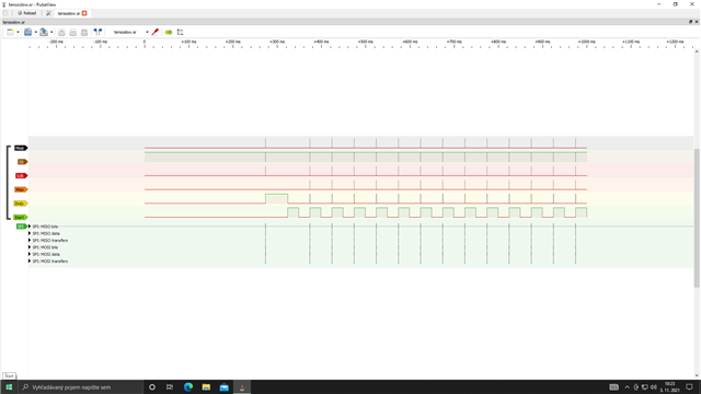
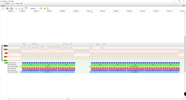
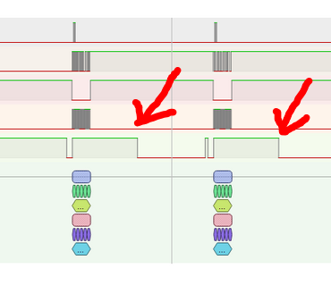
Setup sequence with fast START signal - after this nothing happens.

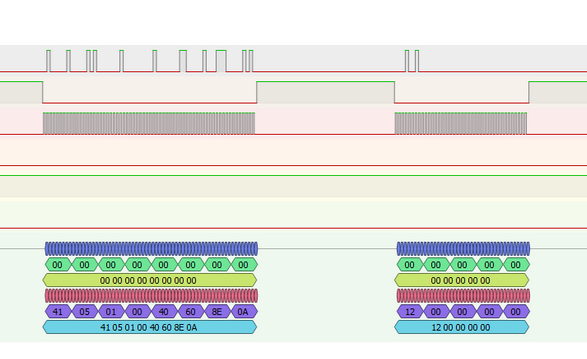
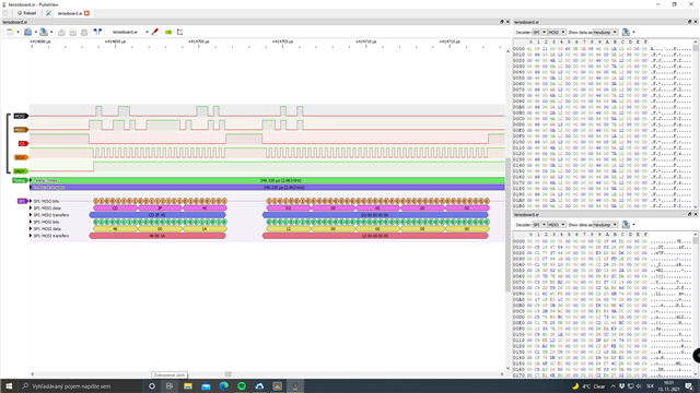
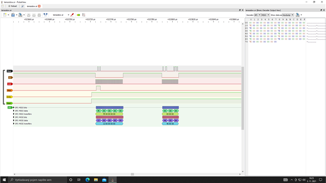
RDATA + WREG INPMUX with slow START signal. Also dump of communication at MISO line.

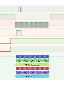
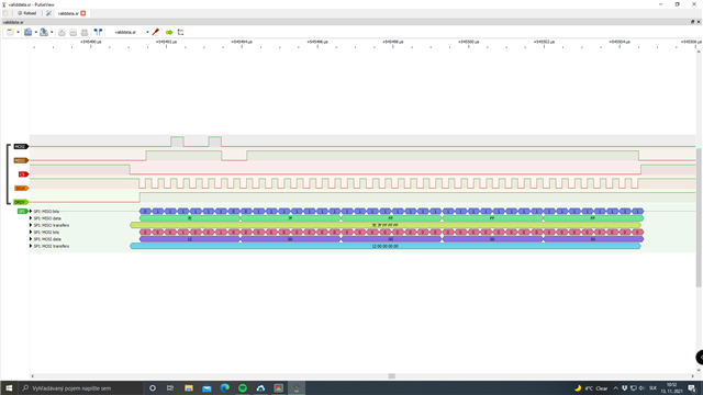
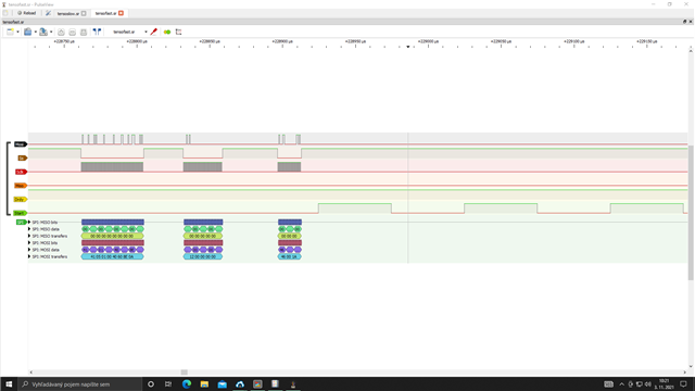
Setup sequence with slow START signal. Also dump of communication at MOSI line.

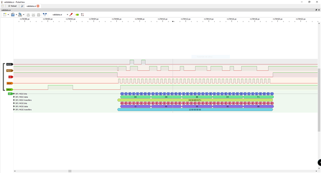
With slow START signal, there are continuous conversions.

  • Hi Stanislav,

    Have you tried reading back the registers after you initialize them, to ensure that they are taking effect? It looks like you are selecting pulse convert mode, but the DRDY pulses from your last screenshot seem to indicate that you are in continuous conversion mode (which is the default configuration of the ADC). See Figure 9-42 in the ADS1262 datasheet.

    -Bryan

  • Hello Bryan,

    Yes, I have checked this. I have also verified all combinations of CPOL/CPHA settings - part is operating in Motorola 1/0 or 0/1 mode, I have finally selected best match to diagrams in datasheet.

    So ADC should be in pulse mode. It is continuously converting, because START signal is pulsing continuously.

    The reason for pulse mode is that I need to scan channels (in other words change mux after each conversion). Can this be done in continuous mode?

    Also I want strict match of conversion speed to 1kSPS/channel (or 10kSPS if we count all channels), data are to be processed in frequency domain.

    Stanislav

  • Hi Stanislav,

    In the first sequence shown below, it looks like you are trying to read data after taking START high, which starts a new conversion - is that correct?

    In the second sequence, you write 6 registers then immediately issue an RDATA command - why?

    I would expect the flow to be as follows:

    1. Initialize your system with a multi-byte register write
    2. Pull START pin high
    3. Wait for DRDY to go low
    4. Pull CS low
    5. Issue RDATA command + 32 SCLKs to clock out data
    6. Change registers e.g. INPMUX (if applicable)
    7. Pull CS high
    8. Toggle START pin
    9. Repeat steps 3-7

    It is not clear from the information you sent that this is the process you are following. The screenshots you sent do not seem to indicate as much.

    -Bryan

  • Hello Bryan,

    I will look in detail at sequences tomorrow.

    Basically, my sequence is as follows. I initialize SPI peripheral, reset ADC, send config. Then for some reason, control gets to DRDY interrupt.

    Now after sending ADC config, I initialize PWM generator, which outputs 50% duty cycle at desired sample rate - this is connected to START.

    In DRDY interrupt routine, I issue RDATA, send data to pc, then write to INPMUX. Next period of PWM generator is supposed to start next conversion.

    Stanislav

  • Hi Stanislav,

    It would be interesting to see a close up of what occurs when you pull START high during the "slow START" sequence, specifically the timing on the DRDY pulse and the commands you are sending to the ADC at this time. Is the data still all 0s for the "slow START" sequence?

    You could also try enabling the CRC to help identify any communication errors e.g. bit flips, or at least rule this out.

    You said you want to scan each channel at 1/10kSPS = 100us, is that correct? With 10 channels, you need 1ms to read out all of the channel data. If this is the case, I should point out that the fastest time to convert a channel using the ADS1262 is 207us at a data rate of 38.4kSPS (see Table 9-13). So the absolute minimum time it would take to scan through 10 channels is 10*207us = 2.07ms. This also results in the worst ADC noise performance.

    -Bryan

  • Hello Bryan,

    Well with fast START, ADC is like dead. No conversions, no DRDY....

    With slow START, ~260ns after START rising edge, I get DRDY rising edge. Then MCU reads "data" (which is always all zero) and changes MUX.

    I am kind of lost with these conversion speeds. ADC is rated 38.4kSPS...so now you say that I can't get 1kSPS on 10 channels, or 10kSPS overall?

    Good idea, I will also enable status byte.

    Stanislav

  • Okay, so byte transmitted on MISO, while transmitting RDATA command, has changed. It was 0x7E, now 0x46. That is everything, again all zero - I have activated CRC.

    It is true that while trying to probe data lines, I did some short-circuits while device was powered. I have no suspects for MCU being damaged. However as for ADC, seems that it is damaged - what do you think?

    Stanislav

  • Hi Stanislav,

    Have you tried reading data as I suggested? This last screenshot shows you reading data after pulling START high and after DRDY goes high. I would expect data to be clocked out immediately after DRDY goes low.

    I assume it is possible the ADC has been damaged, but since you are getting data on the DOUT line, and DRDY is toggling, the ADC communication is active and at least some of it is working.

    In your last screenshot, do you have both the STATUS byte and CRC enabled? Was the STATUS byte enabled in the previous image when the data was 0x7E?

    Can you also confirm that the data is being clocked out on the falling edge of SCLK? I cannot tell from the screenshots.

    Can you share your schematic? Perhaps there is an analog issue that is causing the digital not to function properly.

    -Bryan

  • Hello Bryan,

    Do you assume I am reading data on wrong edge of DRDY? I can try inverting this.

    I have already desoldered old ADC, so I will try further experiments on new one tomorrow.

    At first I had both STATUS and CRC disabled (this is that 0x7E). Then I enabled both of them (using CRC mode), this gives 0x46. But we are talking about byte that is transmitted while transmitting RDATA command. If I understand datasheet, this is not yet status byte.

    As I said, I have checked CPOL/CPHA settings. I believe you are talking about this.

    2804.tenso-mother.pdf

    Stanislav

  • Hi Stanislav,

    One thing I noticed on the schematic is that you have separate ground nets for analog (AGND) and digital (GND) ground. Are these separate ground layers, or are there splits in your ground plane? Ideally there should be one solid ground plane for all ground nodes (other than earth ground, potentially). This can certainly cause communication issues.

    Have you tried using continuous conversion mode and just leaving START high? Then, whenever DRDY goes low you issue the RDATA command, clock out data, and send the WREG command to change the MUX. Per the register map (shown below), the ADC automatically restarts the conversion in process once certain registers are written, including the ones that set the gain, data rate, and input mux selection. Therefore you will not have to toggle START at all, as it is not clear that this toggling is actually working (seems like for fast toggling it is not working). Try this mode of operation and see what happens.

    You can also try to read back some of the internal monitors e.g. AVDD, just in case there is something going on with your input signals. Since the AVDD read back is an internal connection, it should work as long as the communication timing is correct and the ADC power is valid.

    Some MCUs are not always consistent with the way the SPI peripheral is designed. So what we call SPI mode 01 might be 00 on an MCU. The point I was making is to just ensure that regardless of your SPI mode that data is latching on the falling edge of SCLK.

    -Bryan

  • Hello Bryan,

    I have separate ground planes for analog/digital part. They are shorted together near power input connector. After domain split, there are voltage regulators (one for digital, one for analog).

    I may try this as well. However, it will be advantageous to have some nice sample rate value (like 1kSPS, 1024SPS,...).

    Anyway, I have simply tried all four modes, two of them are actually working.

    Stanislav

  • Hi Stanislav,

    Given this:

    Anyway, I have simply tried all four modes, two of them are actually working.

    Is there a specific problem I can help you with now? Are you trying to get it working in the other modes? I was under the impression that the system did not work under any circumstances, but it seems like that is not the case. So if you do need further help, please let me know what is working and what is not and I will offer my support for your outstanding issues

    -Bryan

  • I mean, in two of modes, SPI connection is totally dead(severe mismatch). In two of modes, behavior is as on logic analyzer readings we were discussing.

    Okay, I will try tomorrow what has changed by replacing ADC. Also I will try continuous conversion mode.

    Stanislav

  • Hi Stanislav,

    Sounds good, please post your results then and we will try to determine what is going on

    I will say that the split ground plane can cause these issues, as there might be ground bounce or ground potential between the planes, causing the SPI communication to fail. Unfortunately there is no great way to fix this problem without a board spin. Just something to keep in mind.

    -Bryan

  • Hello Bryan,

    Pulse mode, 20Hz START, it works. I am getting 0x7FFFFFFF. I have expected some noise, but I can believe this is conversion result.

    Pulse mode, 10kHz START, idle.

    Continuous mode, I am getting around 2.5kSPS overall. This is way below my desired sample rate.

    Now my last question, why I am getting max. 2.5kSPS, when in datasheet it says 38.4kSPS? The same thing happened to me with MAX11254 - they are all multiplexed ADCs.

    Stanislav

  • Hi Stanislav,

    Can you explain how you determined the 2.5kSPS data rate? I would have expected something ~2x faster. Are you measuring the time between DRDY pulses?

    If you have not done so already, you should be able to switch the mux first before reading out data. So once DRDY drops low, send the WREG command to switch the mux, then issue the RDATA command immediately after. The output data will read from the data-holding register (up until the next time DRDY drops low, where the data will be overwritten). This might speed up the data read a little bit.

    The latency you are experiencing is a product of multiplexed ADCs and the way the digital filter processes information. There isn't anything that can be done about it unfortunately. Each time you switch the mux, the digital filter assumes a step change and needs to "fill up" again, requiring the latency time mentioned in Table 9-13.

    This could be avoided by using a simultaneous sampling ADC (such as ADS131A04) or multiple ADCs (such as 2x ADS1262).

    -Bryan

  • Hello Bryan,

    Yes I have counted time between DRDY falling edges.

    Now I understand. I kind of don't like multiplexed ADCs for this.

    Thanks for your time.

    Stanislav

  • Hi Stanislav,

    Yes, multiplexed ADCs have their use-cases, but they can be tricky sometimes for higher speed systems.

    If you want a low-noise simultaneous sampling system, I would recommend something like the ADS131A04 + INA849.

    Or you can consider a discrete mux + INA + 1-ch higher speed ADC. We just released the ADS127L11, which is a very high speed, 1-ch delta-sigma ADC. The INA849 might have sufficient bandwidth to drive this ADC, and the ADS127L11 certainly has speed modes to be able to measure 10 channels in <=100us/ch, assuming an external mux.

    Let me know if you need additional support on this topic.

    -Bryan

  • Hello Bryan,

    I do not need additional support at this time. If required later, I will let you know.

    Again, thanks for your time.

    Stanislav

  • Hello ,

    Okay, next level. I configure ADS1262 in continuous mode. Upon DRDY falling edge, I readout data and write to INPMUX (no change if I swap these two operations). And "magic" happens, I have load cells connected, but I read 0x00000000. Absolutely no noise, no bias,...nothing. I have checked voltage coming to ADC inputs, it is not that steady.

    If I issue RREG command, I get proper values. If I change to pulse mode, I only get one conversion result. So SPI is definitely working.

    Stanislav

  • Hi Stanislav,

    Thanks for sharing this additional information.

    Can you please summarize what issue you need help with at this point in time? We have exchanged a lot of information so I just want to be clear how I can support you.

    I believe it is that you are still getting all zeros from the ADC when you read back data - is that correct? If so, have you tried reading any of the internal monitoring channels e.g. AVDD, DVDD, internal temp sensor, etc. to see if that produces valid results? You can also try shorting the ADC inputs together and trying to measure back the ADC noise. This should match the values seen in Table 8-1.

    If you get nothing from the ADC in all cases, then there still could be an issue with the ground planes. Or it is possible that the ADC was damaged during the tests. Let me know.

    -Bryan

  • Hello Bryan,

    That is correct. Currently, issue is that reading is all zeros. I have not yet tried these channels.

    Ground planes, what issue are you talking about? AFAIK, separate digital/analog power domains are widely used to enhance analog performance (isolating digital noise from analog circuits).

    In the same way, I have shorted AGND and DGND in single point. Also, both AVDD and DVDD originate from same supply, but they are separated before voltage regulators.

    Stanislav

  • Hello Bryan,

    With every MUX config I have tried, first reading is all zeros. Then I get reasonable values. But once I change MUX, again first reading is zero. Is this some property of the ADC?

    I can discard first result, but this will halve the sample rate.

    Stanislav

  • Hi Stanislav,

    Assuming the SPI communication is correct, you should not have to discard the first data.

    Can you send the complete data transaction from your logic analyzer? That is the first command you send, DRDY going high, DRDY going low, data read back where data is all zeroes, then the next transaction where data is valid. I just want to make sure that all of the timing, etc., is being met.

    -Bryan

  • Hello Bryan,

    I have already desoldered wires tapped to SPI interface, and I prefer not to solder them again (mainly to avoid short circuit and ADC damage). What I will certainly try ASAP, is toggle some MCU pin from ISR. I feel like there is a mismatch between sample rate measured from DRDY, and observed as incoming packets rate on PC. This could be caused by DRDY misrecognition inside MCU.

    Stanislav

  • Hi Stanislav,

    If this is too problematic then it is okay. Perhaps it is sufficient to know that this should not be happening, which allows you to track down the root cause.

    There are very few circumstances under which the data read back should be all zeros (maybe after powerup but before initialization). The information in the data-holding register should be held there until it is overwritten by new data, and it is highly unlikely that you would be able to measure a 32-bit value that is exactly 0x00000000. So you might want to check to see if the RDATA command is actually being recognized by the ADC the first time you send it (when you get all zeros). It would make more sense that there is nothing on DOUT during this time, which is why you are seeing zeroes, as opposed to 0x00000000 being the value actually stored in the data-holding register.

    -Bryan

  • Hello Bryan,

    Here are LA recordings. If I change MUX after every sample, I get zeros. Then I have removed MUX changes, unfortunately I was not able to reproduce valid results. I got 0x7FFFFFFF and some glitches on DRDY - they may be on LA probes.

    Are you willing to install Sigrok's Pulseview on your computer? Then you would be able to directly open LA recordings.

      LA.zip

    Stanislav

  • Hi Stanislav,

    SCLK is idling high in the images you just sent. This is not the correct SPI mode for the ADS1262. SCLK should idle low

    -Bryan

  • Hello Bryan,

    You are right. I must have switched it sometime. But unfortunately, it is only half solution.

    With only single channel active, it is working. What I do not understand are short pulses on DRDY right before RDATA.

    Upon boot, first RDATA command does not have this pulse. Then it is always appearing.

    Then I add WREG INPMUX command, nothing else has changed. On RDATA command, I am getting 0x00000000.

    Data on MISO during WREG command and opcode byte of RDATA command look like they might be conversion results. Am I using incomplete RDATA sequence?

    And those additional pulses on DRDY disappear.

    Stanislav

  • Hi Stanislav,

    I would assume those short DRDY pulses are there to indicate that data is ready to be clocked out. This matches Figure 9-42 in the ADS1262 datasheet. Is there any reason you do not send the RDATA command when DRDY pulses like this? You are also not sending the RDATA command the first time DRDY drops low (see image below). You should be looking for any instance of DRDY transitioning high-to-low and then send the RDATA command. It is unclear to me how you determine when it is appropriate to send the RDATA command.

    -Bryan

  • Hello Bryan,

    I was using interrupt controller for this. Now I have also tried polling mode - I remember last known state of DRDY line and look for falling edge.

    It is not working either way, I am simply always getting 0x00s. Only thing that works is to keep MUX config until I get nonzero sample. This way, I was able to get stable ~256SPS(on each channel) in pulse conversion mode.

    How should ADC behave when I miss sample? But also on any interrupt/flag line I would expect signal to stay for a fixed time in active state - that is the case for single-input scenario. In my multi-channel scenario this pattern is distorted - I have no idea what this means.

    Stanislav

  • Hi Stanislav,

    Can you try clocking out data first then issuing the WREG command to change the mux?

    Also, what is the START pin doing during this time? Are you just holding it high? It seems like you might be in pulse convert mode, but I would guess it makes more sense for you to be in continuous conversion mode where you could just leave START high. The WREG command automatically restarts the conversion, so that gives you one less pin to worry about

    -Bryan

  • Hello Bryan,

    I can try this tomorrow, hopefully it will make difference.

    I have tried continuous conversion mode, while holding START either high or low. Alongside the issue with 0x00s, sampling rate is a bit unstable. For this reason, I still prefer pulse conversion mode, where I can apply precise signal to START.

    Stanislav

  • Hi Stanislav,

    Understood about the desire to use pulse convert mode. If this works for you then it is certainly acceptable.

    Let me know what happens tomorrow.

    -Bryan

  • Hello Bryan,

    I realized, I already had first RDATA, then WREG INPMUX. Funny thing is, I only commented line:

    if (AdcSample != 0x00000000)

    And it started working. Another thing is, there is still something weird with the samples. Upon boot, they are steady at 0x7FFFFFFF. When I short single channel (ninv with inv), all channels jump to around 0x20000000. Then they slowly approach 0x7FFFFFFF (with some noise) and stop there.

    How can I make such strong crosstalk? Or what is going on?

    I will look at it sometime, but I first need to mount load cells somewhere.

    UPDATE: When I actually connect load cells, I am not getting crosstalk.

    Stanislav

  • Hi Stanislav,

    Thanks for the update. With the channels unbiased, they will likely float to one of the supplies, which seems to be what happened before you attached the load cells.

    Is everything else working now? Has your issue been resolved?

    -Bryan

  • Hello Bryan,

    Yes, everything seems to be okay now. Big thanks for all your support.

    With load cells mechanically unloaded, I have got reasonably low noise levels. I can also see small peak at almost exactly 50Hz (power line).

    With load cells connected to vibration generator(motor with excentric element), I can see strong peak at frequency, which I believe matches motor RPM.

    Stanislav

  • Glad to hear it.

    The ADC has the option to reject 50/60Hz noise, but can only do so at very slow data rates. You would probably have to post-process the data to filter out these spikes.

    -Bryan