This thread has been locked.

If you have a related question, please click the "Ask a related question" button in the top right corner. The newly created question will be automatically linked to this question.

DAC80502: I2C mode

Part Number: DAC80502

I am in trouble because I2C communication is not possible.
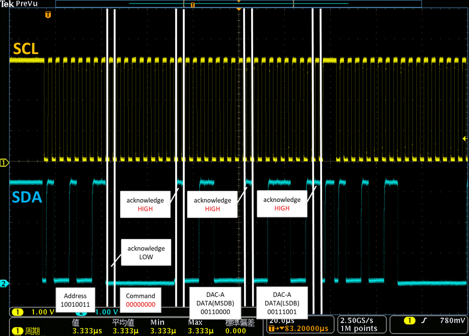
When checking the signal waveforms of SCL and SDA with oscilloscope, the voltage of SDA was LOW from after Acknowledge after sending the address byte to during the transmission of the command byte.
I suspect that SDA could not recover from Acknowledge.
There was no problem with the Timing Requirements for I2C Fast Mode.
I don't know the cause.
Please let me know if there is anything else to check.

  • Hello,

    I think more information would be useful here. The point you make about recovery is an interesting one. I would like to ask what is the size of the pull-up you are using on the digital interface lines?

    Best Regards,

    Gavin Bakshi

  • Hello Gavin,

    The power supply of the digital interface line is 3.3V, and the pull-up resistor is 3.3kΩ.

    Best Regards.

  • Hi, can you share your schematic? Can you confirm that the address you are sending matches the address of the device (thought I recognize that it appears to be ACKing the first byte).

    Thanks,

    Paul

  • Hello Paul,

    The schematic is below.


    -Connect the VDD pin and SPI2C pin to a 5V power supply.
    -Connect the RSTSEL pin and AGND pin to ground.
    -The SDA pin, SCL pin, and A0 pin are pulled up by a 3.3V power supply and are connected to the FPGA pins (FPGA_SDA, FPGA_A0, FPGA_SCL), respectively.
    -The 3.3V power supply starts up after the start-up of the 5V power supply.
    -When inputting HI to SDA, FPGA_SDA is set to high impedance.
    -FPGA_A0 is Hi, and 3.3V is input to A0.

    When checking the signal waveform of A0 pin during I2C communication with oscilloscope, 3.36V was always input.
    So I think the slave address matches the sending address "1001 001".

    Best Regards.

  • Hi, it looks like in your example, you are sending a read command (the r/w bit in the address is 1), but you are reading a NOP address.  Can you try reading another address? What happens when you send a write command?

  • Hello Paul,
    Thanks to you, the problem has been solved.

    I noticed that I misunderstood that the r / w bit should be 1 when using the write command.

    When I set the r / w bit to 0 and sent the write command, I was able to communicate without problems.

    The waveform shown above was taken after communication with the r / w bit set to 0 on the assumption of the write command several times, so I think that SDA has gone wrong.

    Best Regards.