This thread has been locked.

If you have a related question, please click the "Ask a related question" button in the top right corner. The newly created question will be automatically linked to this question.

DAC81416EVM: DAC81416 EVM output not varying.

Part Number: DAC81416EVM

Hi TI Team
We are working on DAC81416EVM. Below is the jumper setting used:
  • J9 - closed
  • J2- open(Reset_L is deactivated)
  • J3-open
  • J12-( 1-2) (VSS=GND)
  • J11- open (We are using internal reference)
  • J10- (1-2) (VIO voltage from J8)
VDD/VAA is provided using an external power supply (5V). 
  1. For normal operation do we need to provide VCC voltage? or should leave this Pin floating? If this pin requires power what should be the voltage?  As per the datasheet, the VCC pin should be powered with 9 V to 41.5V. But we don't want DAC output in this range. Since we need DAC output to be  0V- 5V range. Is it fine if it is powered with 5V?
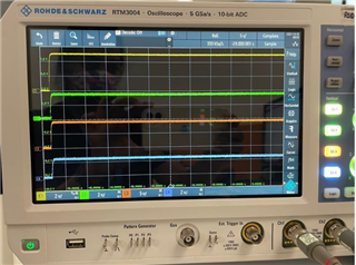
  2. When we probe the reset signal, it is always high. Reset is probed in the below sequence:
    • VDD/VAA = 5V
    • Connect USB2ANY to PC
    • Open DACx1416EVM tool.
As soon as the tool is opened, Reset lines went high. Do we need POR or not?
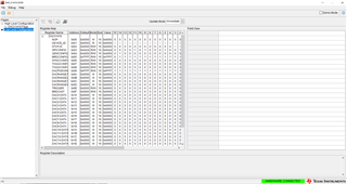
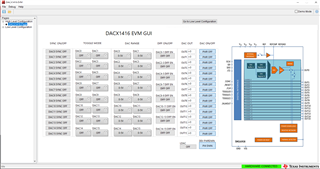
       3. In the DACX1416 tool, the registers are configured as shown below figure. But DAC output is not at all varying irrespective of any value.
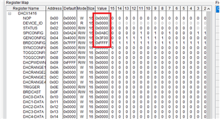
Could you please share your feedback on the same?
Regards,
Vidhya
  • Hi Vidhya,

    1. The EVM requires an external VCC voltage to be applied.  That voltage must be ≥9V.  The device requires a minimum VCC of 9V even if you are only using the 5V range.

    I believe the device on the EVM is staying in a power-down state as the VCC supply is not applied.

    3.  Please start by reading the DEVICE_ID register to confirm that that you have communication with the DAC and it has left the power-down condition.

    Thanks,

    Paul 

  • Hi Paul,

    Thanks for your reply.

    Even with VCC=10V, the device is not detected in the tool.

    All the power VDD/VAA=5V, VCC=10V, VSS=GND is provided using external supply, and VIO=3.3V is provided using J8 connector. And the jumper connection remains the same as said before.

    Is any connection is missing? If all the power supplies are provided properly device should get detected automatically or do we have to do any settings in the tool?

    Regards,

    Vidhya

  • Let me loop in Akhilesh, as he has a bit more experience with this design.

  • Hi Vidhya,

    I would like to know whether you are getting 3.3V VIO voltage from USB2ANY?

    Can you probe test point TP5 and measure?

    if not, please enable 3.3V from USB2ANY.

    Regards,

    AK

  • Hi Akhilesh,

    I have probed at TP5 and measured the voltage it is 3.3V. 

    3.3V from USB2ANY is getting generated and the same we are using for VIO using jumper setting.

    Regards,

    Vidhya

  • Hi,

    Basic question GUI is in demo mode? If yes, you need to uncheck the same ( top right side)

    Regards,

    AK

  • Hi Akhilesh,

    The GUI is not in Demo mode. 

    Regards,

    Vidhya

  • Hi Vidhya,

    Do you have any current limit on VDD/VAA supplies? We need min 30mA

    RESET line from USB2ANY still shows high?

    Regards,

    AK

  • Hi Akhilesh,

    There is no current limit to VDD/VAA supply.

    VDD/VAA is supplied from the DC power supply (0-30V/3A ) and Yes, the Reset line is always high.

    Regards,

    Vidhya

  • Hi Vidhya,

    POR is generated internally as soon as power supplies become valid.

    RESET is active low input, so device should be in active state ( USB2ANY  /RESET should be high after power up).

    When you are launching EVM GUI for the first time, Can you share the screenshot of the same?

    Regards,

    AK

  • Hi Akhilesh,

    Please find the waveform below: Waveform is captured upon power ON.

    Even after launching GUI, no toggling is seen in the reset line. POR is not happening. 

    CH1: VDD,CH2: VIO,CH3: VCC,CH4: Reset_l

    Is there any sequence for powering ON the device?

    Regards,

    Vidhya

  • Hi Vidhya,

    There is no power sequencing required for this device. In Channel 4, RESET high is 3.3V? I am reading the same as less than 3V

    Similarly VCC is greater than 9V?

    Can you share the screenshot of the GUI  after power up?

    Regards,

    AK

  • Hi Akhilesh,

    Below is the screenshot of the GUI after power-up.

    As per the GUI(High-level configuration file) - the device is in power-down mode.Even after enabling the power-down mode, no changes are seen.


    Regards,
    Vidhya

  • Hi Vidhya,

    In earlier posts, you said, GUI was not connecting to EVM. As I can see GUI is detecting the EVM correctly. Wasted too much time for debugging Slight smile

    Go to Low level configuration page and write below registers.

    WRITE SPICONFIG (0x03),0x0A84 // Power-on Device, Disable Soft-toggle
    WRITE DACPWDWN (0x09),0x0000  // Power on all DAC channels
    WRITE DACRANGE (0x0A),0x0000  // Range condigured for 0 to 5V
    WRITE DACRANGE (0x0B),0x0000  // Range condigured for 0 to 5V
    WRITE DACRANGE (0x0C),0x0000  // Range condigured for 0 to 5V
    WRITE DACRANGE (0x0D),0x0000  // Range condigured for 0 to 5V
    WRITE GENCONFIG (0x04), 0x2000 //  Enable Internal reference
    
    /// Write DAC Channels //
    
    WRITE DAC_DATA (0x10), 0x8000 //  dac 0  
    

  • Hi Akhilesh,

    In the earlier post, I stated GUI is not in demo mode( That means EVM was detected). Sorry, if I wasn't clear enough.

    EVM is getting detected in the GUI, the problem was "Device ID" is not getting detected in the GUI. Will the device will work as intended without reading the device ID?

    Also, Register values are configured as per the above value. In this case, DAC 0 output was 9V when measured.

    But, once DAC0 output reaches 9V, if I write any other value to DAC_DATA(0x10), the output is not changing and the device ID is still 0x00

    Regards,
    Vidhya

  • Hi,

    After the above register writes, DAC0 output should be 2.5V, since we configured the device for 0 to 5V ( DAC _DATA is 0x8000). If you are getting 9V at DAC0, I am suspecting some short or device damage.

    are you getting internal reference output at TP12?

    Can you provide +15V as VCC and try?

    You should be able to read DEVICE_ID after the register writes.

    Regards,

    AK