Hello.
I want to obtain a demodulated signal of a continuous wave with a center frequency of 22 MHz. I want to obtain the Doppler frequency component on the baseband side through the LNA -> 3rd LP filter (30 MHz) ->ADC -> Digital Demod process. However, even if it is set as below, LVDS output doesn't come out as the desired data format.
1) First, set the VCA Register as follows. And although there is only channel 1 that is actually used, SCID0_SEL='11' is used to set the Demodulator Register by activating all channels.
First, the Coefficient RAM is set, and the LVDS output is packed with 16 bit of Inphase and quadrature data inside the FPGA with Decimation factor = 3.
According to the AFE5809 Datasheet I understood, when M=3, the data should come out in a repeated form of [A.I, A.Q, zeros. However, output repeats every 40-50 frames in the form of [data zero data zero]. No matter how much I looked at it, I couldn't figure out where was wrong in the SPI setting. Can you take a look at this?
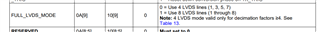
Fig 1. AFE5809 SPI register setting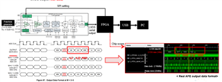
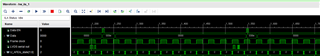
Fig 2. Undesired data format when M=3
2) 22 MHz clock is added as the main input clock of the AFE chip. It is also curious whether demodulation is possible by 22 MHz, which is the same frequency as the main clock within the AFE chip.

-
Ask a related question
What is a related question?A related question is a question created from another question. When the related question is created, it will be automatically linked to the original question.