Because of the Thanksgiving holiday in the U.S., TI E2E™ design support forum responses may be delayed from November 25 through December 2. Thank you for your patience.

This thread has been locked.

If you have a related question, please click the "Ask a related question" button in the top right corner. The newly created question will be automatically linked to this question.

ADS7029-Q1: Design without Opamp as Input Driver

Part Number: ADS7029-Q1
Other Parts Discussed in Thread: ADS7959

Hi Team,

I'm working on a design that uses a 8:1 mux in front of the ADS7029 and I'm trying to understand if the ADS7029-Q1 can realistically be used without a Opamp input driver.

I do not need to sample very quickly at all (millisecond range at fastest), what other risks/tradeoffs do I need to be aware of if we remove the input driver?

Best,

David

  • Hello David

    The ADS7029 could be used without a driving input buffer, but as you noted, the sampling rate is the most important factor in this. 

    When adding a buffer, this does become a bit more complicated as the input source now needs to also drive the MUX impedance as well. 

    I would like to suggest to look at the ADS7959-Q1, this sounds like a much better fitting device based on what you shared. This device has a 8:1 internal mux, with the option of a common driver op amp. If it is not needed, then one does not need to be used. 

    Regards

    Cynthia 

  • Hi Cynthia,

    Thanks for the reply! This is an extremely price sensitive application so the ADS7959 can't get to where we need from that perspective.

    Is there any collateral or formula you can point me to that breaks down achievable sampling rate given external impedances/circuitry and how I should size any filtering components between the MUX and the input of the ADC?

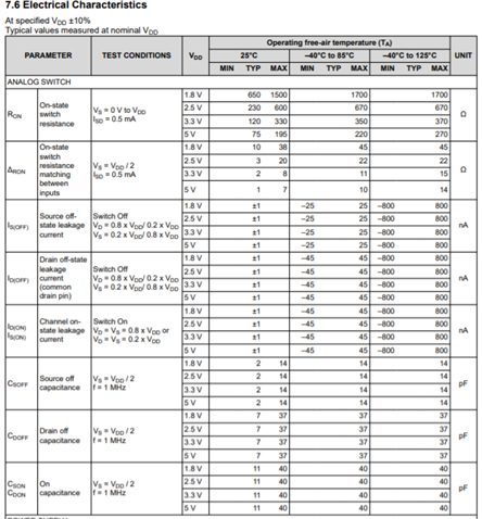
    For reference we are planning to use the TMU1308-Q1. Here are the electrical parameters of it:

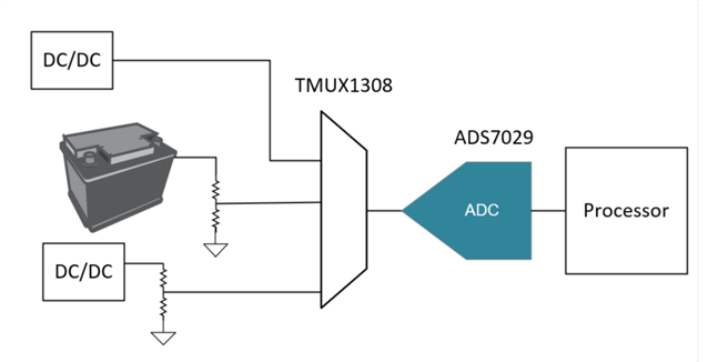
    This will be used to monitor different supplies so the the overall block diagram will look something like this:

    Best,

    David

  • David, 

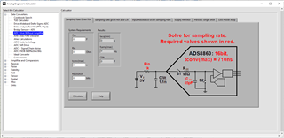
    We have a downloadable tool: Analog Engineers Calculator that can directly help with this. 

    Once downloaded, under "Data Converters" select ADC Drive Without Amplifier. 

    Here are multiple tabs available to find different information. as an example, if you know the sampling rate, it will give the allowable impedance, and vice versa

    Based on the block diagram provided, I would suggest the third and fourth tabs "Input Resistance Given Sampling Rate" and "Supply Monitor" 

    Let us know if you have any questions on the tool.

    Regards, Cynthia

  • Thanks Cynthia,

    Am I looking at this correctly that my worst case Rin needs to be less than the tool's calculated value to make sure we get a proper sample?

    Also is there a whitepaper anywhere that shows the actual calculation steps so I can understand better?

  • David,

    I'm helping Cynthia out as I helped develop this tool.  If you download the tool you will see that the help file has a lot of detail on how to use the tool as well as some theoretical formulas and background on the problem.  Also, there is a precision labs video that covers the theory behind the tool in detail (see link below).  

    https://training.ti.com/ti-precision-labs-driving-sar-without-amplifiers?context=1139747-1140267-1128375-1139106-1147744

    I understand that you want to scan all 8 channels quickly (1 ms / channel).  Do you need to run this scan continuously or do you do one fast scan of the 8 channels periodically?  In other words, do you want to scan all 8 channels in 8ms, but then wait before you rescan the channels (periodic single shot) or do you just continuously read at a rate of 1ms / channel (continuous sampling).  If you are doing periodic one-shot this makes it easier to get fast sampling with large resistors.

    What is your input impedance Rin?

    Can you confirm your maximum sampling rate?  Is it 1ksps (1ms for each channel)?

     Thanks for helping with my questions.  I  hope this tool can help you quickly design your circuit.  FYI.  Once we have done the design, we can simulate the circuit as an extra level of verification.

    Best regards,  Art