This thread has been locked.

If you have a related question, please click the "Ask a related question" button in the top right corner. The newly created question will be automatically linked to this question.

ADS1299: ADS1299 always returns 0x0000 in Single-shot mode.

Part Number: ADS1299

Hello TI,

I'd like to use the Single-shot mode of ADS1299.

I set the registers like below.

========

CONFIG1 : 0x90
CONFIG2 : 0xC0
CONFIG3 : 0xE0
LOFF : 0x00
CH1SET : 0x60
CH2SET : 0x60
CH3SET : 0x60
CH4SET : 0x60
CH5SET : 0x60
CH6SET : 0x60
CH7SET : 0x60
CH8SET : 0x60
BIASSENSP : 0x00
BIASSENSN : 0x00
LOFFSENSP : 0x00
LOFFSENSN : 0x00
LOFFFLIP : 0x00
GPIO : 0x0F
MISC1 : 0x00
MISC2 : 0x00
CONFIG4 : 0x08

========

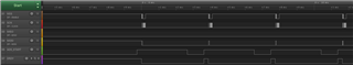
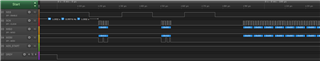
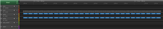
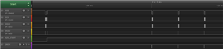
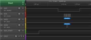
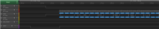
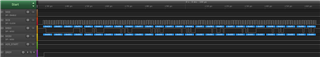
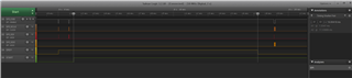
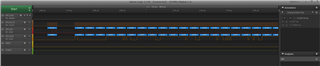
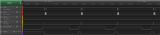
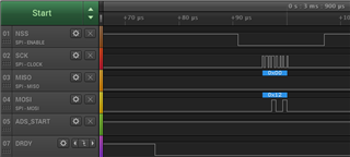
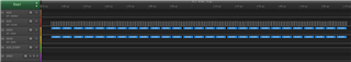
And, When START signal goes high and DRDY signal goes low, I send the RDATA command(0x12), then activate 216 SCLKs ( that is 216bit = 27byte read). ( please see below image)

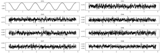
However, read data is always ALL 0, even though CH1 is connected to SIN wave of function generator.

So, could you please tell me how to control ADS1299 in Single-shot mode ?

Thanks.

  • Hi Tomohiro-san,

    Thanks for the post.

    You send the correct digital sequence for the Single-shot mode and RDATA for data retrieval based on your logic analyzer waveforms. Weirdly, you are not seeing any data toggling on the output. Can you issue the SDATAC command prior to the single-shot mode and RDATA operation? Would you please check to see if you are able to get the device ro return any data in the Continuous conversion mode with RDATAC data retrieval?

    Thanks

    -TC

  • Hi TC,

    Thank you for your reply.

    I've tried your suggestion (SDATAC command prior to single-shot and RDATA command), but the read data unfortunately keeps 0x0000. Please see below image.

    [Overall]

    [Expand a part of SPI communication]


    Also I've tried Continuous conversion mode with RDATAC with the below register setting.

    ========

    CONFIG1 : 0x96
    CONFIG2 : 0xC0
    CONFIG3 : 0xE0
    LOFF : 0x00
    CH1SET : 0x60
    CH2SET : 0x60
    CH3SET : 0x60
    CH4SET : 0x60
    CH5SET : 0x60
    CH6SET : 0x60
    CH7SET : 0x60
    CH8SET : 0x60
    BIASSENSP : 0x00
    BIASSENSN : 0x00
    LOFFSENSP : 0x00
    LOFFSENSN : 0x00
    LOFFFLIP : 0x00
    GPIO : 0x0F
    MISC1 : 0x00
    MISC2 : 0x00
    CONFIG4 : 0x00

    ========

    Continuous mode looks good for me. The read data is not 0x0000. Please see below.

    [Overall]

    [Expand of 1st SPI communication]

    START signal became HIGH, and RDATAC command was sent.

    [Expand of 2nd SPI communication]


    When DRDY become LOW, SPI transaction of 27 bytes starts. The read data is not 0x0000, and restores the sine wave.

    Only CH1 is connected to function generator.

    Can you please tell me how to control correctly in Single shot mode ?

    Thanks.

  • Hi Tomohiro-san,

    Thanks for the additional test information. Please let me take a look at get back to you?

    Thanks

    -TC

  • Hi TC,

    OK, thank you for your reply. I appreciate your support. I'll wait for your investigation.

    Thanks.

  • Hi Tomohiro-san,

    Thanks for the patience.

    For the Single-shot mode with RDATA command, you will need to make sure that you keep the CSB low after sending the RDATA command. Please refer to Figure 47 in the datasheet for the RDATA timing diagram. The SPI interface will reset if you pull the CSB high after sending the RDATA command, causing the current conversion data to be lost.

    Thanks

    -TC

    [Overall]

    [Expand of 3nd SPI communication]


  • Hello TC

    Thank you for your reply! The issue could be resolved by your appropriate answer.

    Thanks.