Hi team,
Could you tell me the input impedance of the ADS1115's A0~3? (I'm using the Adafruit module)
Best wishes,
This thread has been locked.
If you have a related question, please click the "Ask a related question" button in the top right corner. The newly created question will be automatically linked to this question.
Hi team,
Could you tell me the input impedance of the ADS1115's A0~3? (I'm using the Adafruit module)
Best wishes,
Thanks for the reply.
One thing I didn't understand well is is the correspondence between the "modes" listed in each document. When using the ADS1115 module, I can choose between "Single-ended mode" and "Differential mode" according to my application (Please refer to the URL link below).
I don't know whether each of these two measurement methods corresponds to "differential" or "common-mode" in the datasheet (or whether they are related at all).
If the impedance changes depending on the measurement method, then I will need to modify my circuit accordingly.
Regards,
The impedance values listed remain the same. The circuit is what changes if using differential vs single ended.
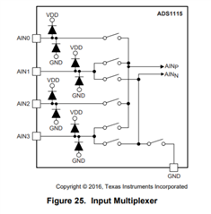
If you are using single ended, then the AIN_N is then connected to ground, refer to the circuit diagram below. the switches will change position based on what mode (single ended vs differential) is used. From here, take the circuit from above and replace AIN_N with ground.
Zdif = differential impedance values, Zcm= common mode impedance values

Regards
Cynthia
I see, I misunderstood.
If that is the case, how can the overall input impedance be calculated when trying to measure the potential difference at A0 and A1 of a module in "differential mode", for example?
Will it be the composite of Zdif and Zcm?
Mai,
Correct, once you decide what configuration the switches will be in, you can then analyze the circuit.
Regards
Cynthia
Thank you for your kind answer!
When I measure in the single-ended mode from A0 of the module with FSR≈6.1422, I think the input impedance will be 1/((1/10M)+(1/22M)), is that correct?
Then, if you measure in the differential mode from A0 and A1 with FSR=6.1422, how do I calculate the input impedance at each pin?
How should I take into account the 0.7V in the diagram?
Mai, I hope you were able to move forward, I will be closing this thread