This thread has been locked.

If you have a related question, please click the "Ask a related question" button in the top right corner. The newly created question will be automatically linked to this question.

ADS1230: AD result periodically changed

Part Number: ADS1230

Hi,

I met a problem during I use ADS1230 to measure the output of a strain gauge.  I found even the output of the strain gauge is close to zero, the AD result periodically be very high, the duration is from several seconds to several tens seconds.

I captured the waveform of DOUT/DRDY and SCLK and found if there is no any problem, the waveform is stable; however the data ready time is periodically changed.

The waveform is as below:


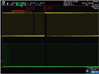
CH1(Yellow) is the DRDY/DOUT, CH2(Green) is SCLK.

The data ready time is reduced from long to short and then becomes very long and then reduced cycle by cycle.

When this kind waveform appears, the AD result is not stable. A high value appears every seconds or several tens seconds.

In my design, I use the 21st SCLK to force DRDY/DOUT high. But I found sometimes the DRDY/DOUT can not be pull to high after 21st SCLK is available. Please see below picture for this case.

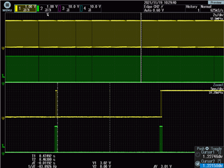
In the picture above, after 21st SCLK be available, the DRDY/DOUT be pulled to high after 11.92 ms. I am not sure why it needs so long time to drive DRDY/DOUT high.

In my design, the cycle of DOUT/DRDY is about 12.1ms.

And I would like to know if the DRDY/DOUT is not ready, for example in above picture if I send SCLK when DRDY is low without the high to low process, what will happen?

This phenomenon is firmware related, I have a firmware without any problem; but another version has problem. The algorithm and code is almost same, I don't know what causes this. The product with this software is OK in last half year but has problem in this month with 20% failure rate. 

Would you please help to resolve this issue.

Thanks in advance!

  • Hi Leo,

    Welcome to the E2E forum!  One of the common issues that I have seen is how and when customers determine when to read the conversion data from the ADS1230.  It sounds like you might be polling the DRDY/DOUT pin.  In the past I have seen customers have no issues running at 10sps, and then start to have issues when running at 80sps.  The result is the processing time to fully capture the data is fine at 100ms intervals, but does not fully complete at 12.5ms intervals.  

    I have also seen timers get used to capture the data at certain intervals.  Here the problem is maintaining timing synchronization between the micro clock and the ADC clock.  The ADS1230 had no provision for synchronization and the free running clocks tend to overlap and data corruption is a result.

    Consider that as soon as a conversion completes it will overwrite the previous conversion result and corrupt the data being read if the completion takes place during the middle of a read cycle.  From your scope shot it would appear that this is what is happening.

    The best results come from using an interrupt driven system.  In this method you do not need to force the DRDY/DOUT high, but instead the interrupt is triggered when the input sees a falling edge triggered event and then immediately the conversion data is collected.  Using this method I have connected DRDY/DOUT signal to both the DIN of the micro and an interrupt capable GPIO.

    If you wish to use the polling method you must make sure that the entire conversion result is read from the ADS1230 before the next conversion result completes.  This means that your polling loop must allow for enough time to process and capture the data.

    Best regards,

    Bob B