This thread has been locked.

If you have a related question, please click the "Ask a related question" button in the top right corner. The newly created question will be automatically linked to this question.

ADS131M02: About DRDY timing

Guru 11170 points
Part Number: ADS131M02


Hello E2E,

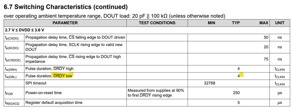
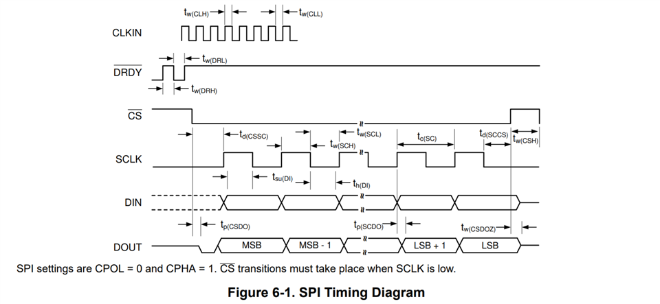
I understand that the DRDY pin will switch to Low when the ADC completes the data conversion.

Normally, DRDY is input to the interrupt trigger of the MCU and then SPI communication is performed with the ADC, but in our usage, there is another priority process, the timing to start SPI communication is delayed, and the next DRDY SPI communication may not end even at the timing.

I'm currently looking at OSR128 and 64 (TBM bit 1) and OSR256.
When the above conflict occurs, the phenomenon that DRDY goes low is usually seen in half the time when DRDY goes low.

For example, if the DRDY is set to be Low in a 128us cycle, it will be wavy if the interval at which the DRDY is Low is constant as 128us-> 64us-> 128us-> 128us.
What time is the latch timing of the ADC data at this time?

Regards,
ACGUY

  • Hello ACGUY,

    According to the datasheet, the nDRDY signal's low duration is dependent on the CLKIN signal as shown below:

    You did not provide CLKIN but 128us would equate to f_CLKIN = 31.25kHz which seems more like a data-rate than a CLKIN frequency. What are your intended CLKIN and data-rate if your setting OSR from 128, 256, and 64? Do you have an oscilloscope or logic analyzer confirming the rate?

    For example in High Resolution mode the CLKIN is 8.192MHz which would be 488ns when the nDRDY would be low before coming high again. Then, the nDRDY toggle low again, or falling edge to falling edge, at a frequency around the data-rate (assuming global-chopping mode is off or GC_EN = 0b0).

    Best,

    -Cole 

  • Hi Cole,

    Tnak you for your reply.
    I want to know the reason why the interval at which DRDY goes low is not constant and becomes shorter.
    Could you comment about it?

    Regards,
    ACGUY

  • Hello ACGUY,

    In general, we don't expect the nDRDY to change the interval time by 100%, it should be linked to the clock's jitter specification which should be around 5-10% on average. Can you answer the questions above so we can understand this unintended behavior?

    Best,

    -Cole

  • Hello ACGUY,

    The DRDYn behavior can change depending on when conversion data is read from the device. In the case where a new conversion is completed while the previous conversion is still being read, the DRDYn pulse is internally gated and blocked from reaching the pin. 

    If a conversion is missed, it can be temporarily stored in the two-sample data FIFO. There is a DRDYn flag for each channel in the STATUS register which will remain set until all data is read. One way to handle this condition is to read back-to-back samples.

    Regards,

    Ryan