This thread has been locked.

If you have a related question, please click the "Ask a related question" button in the top right corner. The newly created question will be automatically linked to this question.

ADS1220: PGA setting usage for PGA>4, Bipolar vs unipolar power supply

Part Number: ADS1220
Other Parts Discussed in Thread: , ADCPRO

Hello,

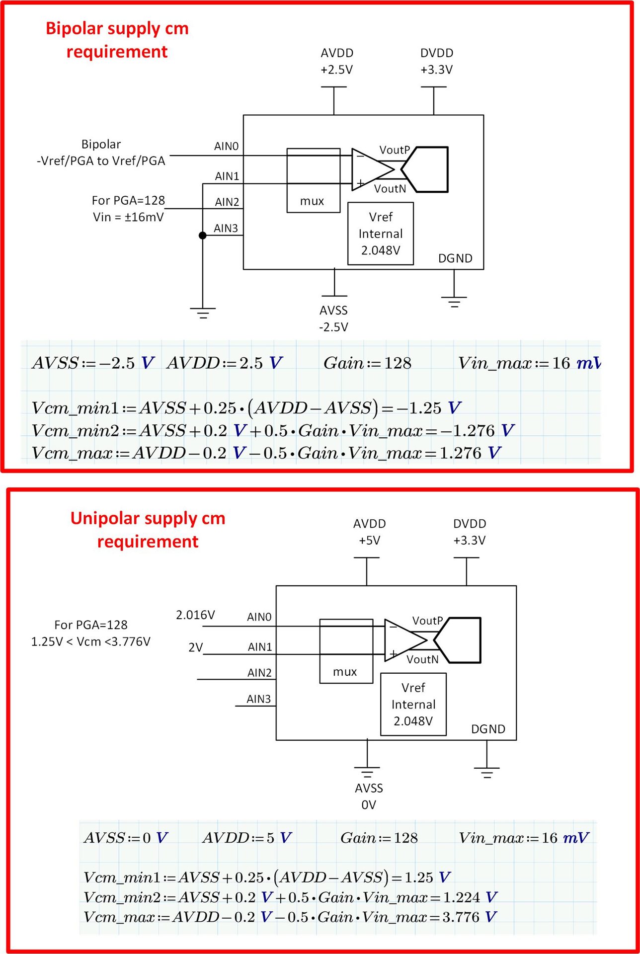
I have a design where I would like to use PGA>4.

Current design has

  • AVDD=+3.3V
  • AVSS=GND
  • Vref=1.024V (external)
  • Ain0=Signal + 
  • Ain1=GND (Signal GND) so, single ended

My newest design requires use of PGAs of higher than 4, so I wonder what hardware and FW option should be set/enabled to make use of full 1-128 PGA range?

I have made several modifications to the PCB already, by de-soldering pins of ADS1220, lifting them and connecting to AVDD=+2.5V, AVSS=-2.5V, RefN/RefP used internally connected to AVDD/AVSS but still am struggling to get correct performance.

Thererofe, I would like to ask you to provide suggestion to the design to be able to measure single-ended signal with full PGA 1 to 128.

If it is needed, single-ended signal can be fed to the ADS1220 as differential, any hardware change there is needed will be implementer.

Thank you in advance.

  • Ilja,

    The key consideration to keep in mind when using the PGA in higher gains is the common mode voltage.  Generally, with ADS1220 single ended measurements are made by connecting AVSS using the internal multiplexer switch as shown in figure 38.  However, in this mode of operation it is difficult to meet the PGA common mode requirements.  The best approach for doing the high gain measurements will be to do them differentially.  With your new bipolar supply configuration, you can connect all the negative mux inputs to GND and your positive MUX inputs to the input signal.  This effectively sets the common mode at mid supply which is the optimal point for PGA common mode range.  I suggest reading through the PGA Common-Mode Voltage Requirements section in the data sheet.  There are some useful equations and graphs that can help you to confirm your common mode range.

    Let me know if this helped or if you have further questions. 

    Best regards, Art

  • Dear Art,

    Thank you for your reply and suggestions. I have read that article 8.3.2.1 of the datasheet however, I still have questions:

    In that section it is not mentioned:

    • what Vref Reference voltage shall be used(in both cases, uni- and bipolar AVDD/AVSS supplies)
    • whether unipolar AVDD/AVSS may be used
      • It is preferred to use 5V/GND as power supply to the IC (AVDD/AVSS)
    • How can a single-ended signal be measured?
      • Our signal is a Gaussian peak referenced to its ground, ranging from 0-to-10V max, attenuated by a resistor divider.

    First I would like to get the hardware part sorted and then get to the Firmware settings,

    so I am looking forward to your reply.
    Thank you in advance

  • Ilja,

    1. I would suggest that you use the internal voltage reference unless you have a good reason to use an external reverence.  One reason to consider an external reverence is it you need ratiometric voltage reference.  Another reason would be if you need a larger input range than the internal 2.048V reference.

    2. The most common use case for the device is to use a unipolar 5V AVDD supply and AVSS = GND.  This configuration will allow unipolar positive input voltage measurements.   If you need negative voltage measurements you will need to use bipolar supplies.  I mention the bipolar supplies because this is what your original question was about.  If your signals are only positive you should use the 5V AVDD and AVSS to GND.

    3.  Please let me know all the different signal ranges you need to measure.  Once you do this I can recommend a hardware connection.

    4. To measure signals greater than AVDD you will need to use a voltage divider.  Once I know your full signal ranges I can recommend a voltage divider.

    I hope this helps clarify the issue.  

    Best regards,  Art 

  • Dear Art,

    Thank you very much for your approach to my question.

    1. I am strongly considering using a 5V AVDD and 5V Vref for maximum input range and highest PGA of 128;
    2. Our signal is a Unipolar 0-10V signal referenced to GND, we do not need negative voltage measurement;
      1. Having read that bipolar power supplies have to be used in order to use PGA higher than 4 and remain linear, I have tried this bipolar AVDD/AVSS(+2.5V/-2.5V) hardware setup.
    3. Our signal range is 0-10V and it is attenuated by a resistor divider with attenuation 1:2,so that we will end up at 5Vmax, protecting the input with a Zener diode;

    4. At this moment I use a Test signal taken from external voltage reference(1.024V DC), which is divided to a value of 5mV and fed to the ADS1220 Ain0 input.

    With our current setup of a Unipolar AVDD/AVSS and TEST input signal at 5mV at Ain0 and GND at Ain1 we see non-linear behavior of readout at PGA>4.

    Our goal is to be able to use full PGA range linearly with unipolar supplies (+5V0/GND) for a single-ended signal of 0-5Vmax (already attenuated value). Kindly ask you to suggest HW setup and FW settings to be able to meet our requirements.

  • Ilja,

    1. Regarding your item 2b.  You are correct, in higher gains the common mode voltage will be out of range when applying a small signal referenced to GND and use a PGA setting greater than 4.  So I understand the issue you are having now.  Your idea for using bipolar supplies should work.  You may be having issues as lifting device pins (e.g. AVSS) and connecting with thin prototype wires will not yield the best results.  You really need a solid power supply connection and decoupling.

    2. Below I show two schematics.  On with a bipolar supply connection, and one with unipolar.  I show the common mode calculation for both connections.  You can see that the unipolar supply configuration requires a common mode voltage of at least 1.25V.  If you are using this configuration to measure a signal that is a few millivolts from GND the common mode would be in the millivolts and well below the 1.25V minimum.  The bipolar case, on the other hand has common mode range of -1.276V to 1.276V so it can easily measure a signal that is a few millivolts from GND (i.e. 0V is right in the middle of the common mode range).  

    3.  You really have three options: a) continue to use the unipolar supply and restrict your gain to 1-4 (PGA bypass mode), or b) use the bipolar supply, c) find some other approach to make sure that the common mode in in range.  Using options b and c add complexity to your design.  With the bipolar supply your input range is restricted to 0V to 1.276V.  With the unipolar supply and PGA bypass mode you have a much wider common mode range.

    4.  I understand that you want to use higher gains for your small signals to get better noise / resolution.  So using the bipolar approach may be a good option for you.  However, look at the noise tables on page 16 and 17.  It may be that you get sufficient noise performance in a PGA bypass gain of 4. 

    5.  Regarding the bipolar configuration that you are using now.  Can you show a schematic?  How bad is the performance?  As I mentioned previously, it may be difficult to achieve good performance by lifting device pins and making connections with prototype wires.  Can you send a picture of your prototype?  

    6.  I assume that you are getting good performance with the old configuration in PGA bypass mode.  Correct?

  • Dear Art,

    Thank you for your detailed explanation and thorough approach in answering my questions. I have in the meantime received an ADS1220EVM to be able to verify your proposal on unipolar supply to ADS1220. I will come back once I have verified it and have clear understanding of operation modes vs PGA>4.

    I highly appreciate you effort.

    Best Regards,

    Ilja 

  • Hello Art,

    I have compiled some ideas and would like to run through your list first:

    1. Clear

    2. Thank you for schematics, I have run some testing and have some ideas/questions.

    3. We are aiming on evaluation of signal processing precision at all PGA settings, that is the key point of the thread.

    4. Our signal is sitting in range of 0-5V coming out from our detector, although based on material detected, the signal can be as low as 50-100mV peak.
    It is important to have all parameters fixed during development and use only 1 set of parameters in final design to be able to detect the lowest 50-100mV signal as precise as the 5V peak ones. In order to achieve that, based exactly on tables from pages 16-17 of the ADS1220 datasheet, I would like to use higher gains in order to find a perfect combination of Noise Vrms and ENOB.

    5. I have discarded all bipolar testing at the moment and focusing on getting good grip of unipolar supply.

    6. We are getting satisfactory performance and are looking forward to possibilities in getting the best.

    Like I said, in the meantime I have made several tests with ADS1220EVM using unipolar supply to validate your proposal of common mode measurement.

    I have observed following:

    1. Whilst we connect our signal carrying lead to Ain0 and our common mode gnd(reference of signal) to Ain1, I would expect settings of the ADCPro MUX to be set to Ain0:Ain1, but I would get normal readouts only in Ain0:AVSS mode. Is it supposed to be set like this in our final firmware? I can not get clear understanding of this mismatch.
    2. After a set of re-test with 2.005V on Ain0 I could not get any decent result out from the ADS120EVM.
      I will attach 2 test documents, Test-1a for 2.016/2.000V (MUX Ain0:AVSS) and Test-1b for 2.005/2.000V(MUX Ain0:Ain1).
      Moreover, if I detach both signal wires from Ain0 and Ain1 and leave these ports floating, I keep getting exatcly the same readouts at all PGA settings as in Test-1a, so that makes me doubt in Test-1a, whereas Test-1b has not shown expected result.
      Could you provide your expertise on what are we seeing here and what setting should be used to be able to use PGA linearily in common mode, unipolar supply?
    3. It is also not clear how is Vref counted? Does it take our common mode voltage (2.0V in your proposed case) and count from there 2.048V up?
      Could you please explain about Vreference in unipolar supply in comon mode?
    4. I am looking forward to evaluating possibility of lifting our detector signal by a pull-up resistor to a level of 2Volts that would allow us to measure in unipolar suply common mode. At this moment that question is being evaluated by detector manufacturer.

    Here is a link for 2 word documents with screenshots and quick description of test setup hardware:

    https://files.fm/u/jxfzxuxk3

    Looking forward to your support,

    Ilja

  • Ilja,

    I cannot access your link (blocked by our security).  Can you just directly past pictures in your updates.  I will look through the details of your post tomorrow.  Also, I will modify my EVM to try and implement the same.  I would like to provide you with a simple step-by-step approach to meet your goals using the EVM.

    Art

  • Dear Art, I have uploaded all the photos from both tests I have described above

    Signal voltages fed to AIN0 and AIN1 are created from on-board 5V0 divided by trim potmeters to 2.016v and 2.000V accordingly.
    Photo of hardware setup(indication of HW setup, 2V lead is to connected to Ain1 during test.):

    Test-1-a
    https://ibb.co/4R32SfY
    https://ibb.co/kGfRdzk
    https://ibb.co/xJQVNr0
    https://ibb.co/x36fLJD
    https://ibb.co/84WBHBG
    https://ibb.co/SNBdC0h
    https://ibb.co/MSHHmHt
    https://ibb.co/gr8S4WZ
    https://ibb.co/gP1cSyQ
    https://ibb.co/gP1cSyQ
    https://ibb.co/87J2JRL

    Test-1-b
    https://ibb.co/khSq9jz
    https://ibb.co/Tr2mYVv
    https://ibb.co/TYGChfd
    https://ibb.co/GVDfcWd
    https://ibb.co/4Y3HK1H
    https://ibb.co/yph0yYv

    Looking forward to your comments

  • Dear Art, Please find pictures of both tests attached.

    Signal voltages fed to AIN0 and AIN1 are created from on-board 5V0 divided by trim potmeters to 2.016v and 2.000V accordingly.

    Test-1a:

    Test-1b:

    Looking forward to your reply.

  • Ilja,

    1.  I still cannot read any of your pictures.  I believe you have them linked to a server.  Under E2E options you can "insert" a picture or file.  That is the only way I can receive pictures.  For future posts when you have many figures you should probably put them in a word document and post a PDF.  However, for now I hope that my post can help you so that you do not need to post further info.
    2. I modified the EVM to match your requirements and collected data.  The results look pretty good (see attachment).
    3. I tried to lift the AVSS lead and tack a wire onto it for -2.5V supply.  This did not work well.  The connection was not robust enough. To fix this issue, I used a separate break out board with ADS1220.  The ADS1220 break out board wires to the ADS1220EVM digital signals, GND, and DVDD.  AVDD and AVSS connect from the breakout board to a +/-2.5V supply.  The input signal is also a precision DC source.
    4. I include trouble shooting tips in the PDF.
    5. Sorry, I can't comment much on your post as I can't see the pictures.  Please look through my attachment and see if this helps you solve the issue.  If not you will need to re-post your pictures (or document) using the insert option.  Note that potentiometers may give ok results but when adjusted to very small output levels they may drift a lot.  Also, the output of the potentiometer depends on how accurate and stable its source is.  

    I hope this helps!

    Art

    ads1220 bipolar measured results.pdf 

  • Hello Art, Thank you very much for detailed approach, I will study your proposed solution. in the meantime I have converted my doc files to pdfs and attached.

    I have verified with manufacturer of our detector that it's baseline may be pulled up by 2V.
    Taking that into account, our preferred way of using unipolar PSU is now possible, so that is why I emphasize on unipolar supply design

    I do not see any options of attaching files directly from my computer, so all PDFs/ photos/ doc files have to be first uploaded to a 3rd party service and then a link has to be provided to be able to attach it to this post.

    I have uploaded my files to:

    https://we.tl/t-xXlhnjdiCE

  • Ilja,

    Below is the instruction on how to post a document.  Sorry for the trouble.  I cannot access your link.  I hope the  instructions help.

    Best reagards,

    Art

  • Hello Art, thank you for the hint, the upload text does not look like a button so that was confusing.

    Please  find my results attached

    ADS1220EVM - TEST-1a-MUX-Ain0-AVSS.pdf

    ADS1220EVM - TEST-1b-MUX-Ain0-Ain1.pdf

    Kind regards,
    Ilja

  • Ilja,

    I was able to look at your attachments.  Very nice documentation.  I can see in the case where you are using PGA gain of 128 that the mux is configured AIN0:AVSS.  This means one input of the ADC is connected to AIN0 and the other is connected to AVSS.  You need to connect the mux to AIN0 and AIN1.  This is actually how you configured for low gains.  Try that and I think you will be able to use the higher gains.  Regarding your input signal you may get a lot of noise and drift as the potentiometer plus supply will not be low noise and low drift.

    I hope this helps.

    Best regards,

    Art 

  • ADS1220EVM - TEST-1b-MUX-Ain0-Ain1.pdf

    Hello Art,

    I have tried both MUX settings, please see TEST-1b document where that setting is selected however the readout doesn't change whatever the PGA is.

    Ilja

  • Hi Art,

    At this moment I have tried different modes of multiplexer and I could not get any amplification of the signal using a common mode unipolar supply.

    Is it possible that you would make a hardware setup based on ADS1220EVM for common mode based on a unipolar supply and ship it to us at the cost of our company?

    Thank you in advance,
    Best regards,
    Ilja

  • Ilja,

    I will contact you via email on this.

    Best regards,

    Art