This thread has been locked.

If you have a related question, please click the "Ask a related question" button in the top right corner. The newly created question will be automatically linked to this question.

ADS1261EVM: Low Bit Incorrect on MISO Echo

Part Number: ADS1261EVM
Other Parts Discussed in Thread: ADS1261, ADS1235

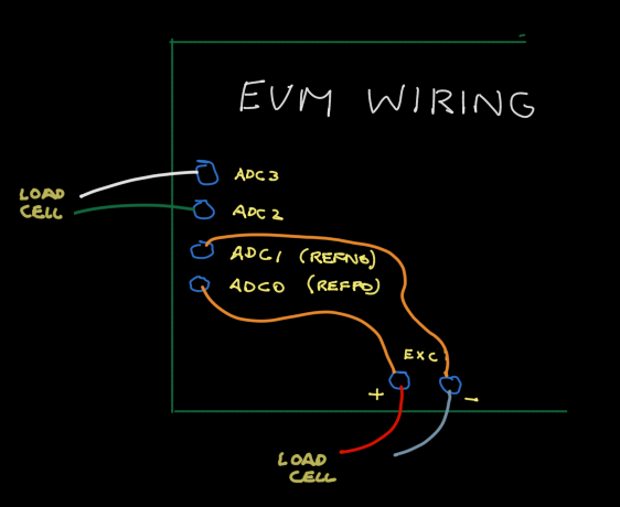
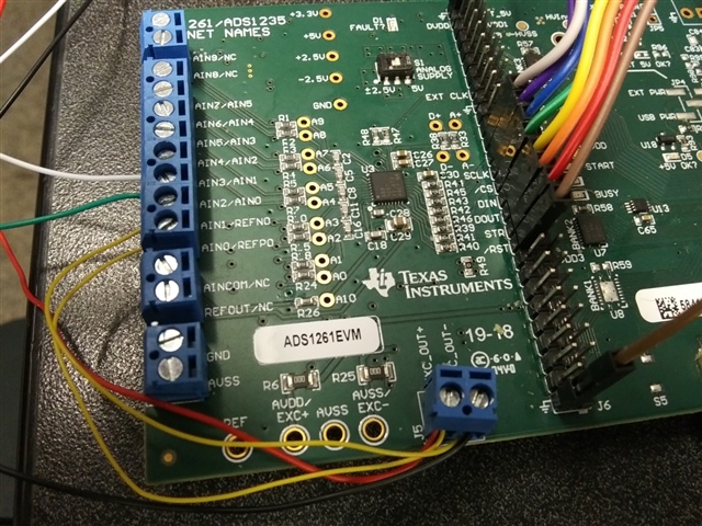
I am using the EVM with a separate ESP32 processor to drive the board.

I juper'd JP1 to tri-state the onboard processor as stated in the manual.

All works well .. Almost.

I send a 0x06 command and the 'echo' returns a 0x07 on MISO.

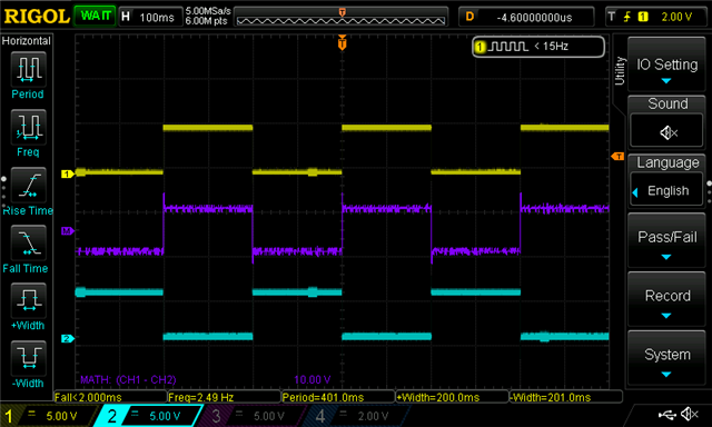
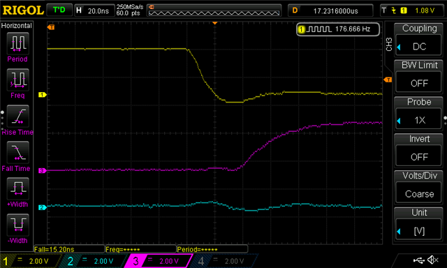
The scope traces tell the story ..

The first trace is the 'overview' .. sending a 0x06 and receiving (supposedly) a 0x06 back.

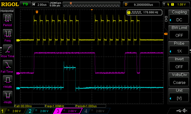
The second trace is a closeup of the last bit .. showing only 40ns for the ESP to catch the zero. It gets a one instead which is why I get a 0x07 back.

The ADS1261 only allows 40ns on the final bit instead of the 'normal' half clock.

This appears to be too fast for the ESP32.

Am I doing something wrong?

The clock is 1Mhz; MSB First; Mode1

The trace order on the scope images is,

Clock (yellow), MISO (purple), MOSI (blue).

Thanks, Tom

  • Hi Tom,

    There appears to be some pretty significant noise on the SCLK line that is coupling into the DOUT and DIN (most notably on DIN). This could certainly be causing issues with the digital communication.

    I would try to isolate the source of this noise and clean it up. Also make sure you have a solid ground connection between the two boards, otherwise communication errors will occur.

    -Bryan

  • Bryan,

    Thank for the reply.

    I've got a star ground (scope, esp32, ADS1261) ..

    I can try to beef it up a bit.

    That however doesn't address the 40ns issue.

    How long am I guaranteed to have the valid low bit present on MISO after the falling edge of the clock?

    The scope shows its only there for 40ns.

    Looks like part of the problem is the double duty of DOUT ..

    From the datasheet ..

    Propagation delay time, last SCLK falling edge to valid
    data ready function on DOUT/DRDY ----> 110ns

    This means the max time I have to sample the last real MISO bit is 110ns .. but what is the min time? .. How fast does my SPI driver have to be?

    If I got it working at 40ns on the ESP32 .. What happens if we change to an alternate platform with different drivers?

    Looking forward to a response.

    Tom

  • Hi Tom,

    What are you trying to accomplish during this sequence? You are sending the RESET command (0x06), but you must also be running conversions. Are you holding the START pin high during this time? Something must be triggering DRDY to go high after the RESET command is clocked in, which is generally the start of a new conversion.

    You could also turn on the CRC to check that the communication transmitted correctly.

    Is it possible to just use the dedicated DRDY pin?

    Timing is shown below for the minimum time to clock out the final bit before data becomes invalid in DOUT/DRDY mode.

    -Bryan

  • Bryan,

    Thanks again for the quick response.

    Some improvement but still errors on the low bit.

    If I were reading it with an FPGA the 15ns would be fine but with a firmware driver it seems to be an issue. I've tried DMA, bit bang (with the ESP32 processor running at 240Mhz). I haven't tried assembler yet.

    I did the following to improve things a bit.

    - Beefed up the ground.

    - Extended the time that CS~ was low after the transaction.

    - Made sure that START was low.

    - I connected a Saleae logic analyzer and it matches my low bit problem. It gets the same error .. most of the time .. but not always. It goes both ways; I get a  correct bit and it gets it wrong, It's wrong and I'm correct, we both get the wrong low bit, or we both get a good low bit. A side note .. With the RESET command MISO goes HIGH after 20ns, and gets a bad echo (0x07) most of the tme,  but on register reads MISO goes HIGH after 40ns (and these work correctly most of the time; see below).

    - Tweaked the SCLK freq .. Below 7Mhz fails all the time ... Above 10Mhz fails all the time. 8Mhz works 95% of the time (so far). I can generally read all registers correctly (95%) at 8Mhz.

    It didn't seem as there was one thing that made it better .. It took all of them ..

    This is a bit scary as I don't want to spend a lot of time (in the final application) handling CRC errors.

    I am now trying to do an actual conversion just so I can think I'm making progress.

    The docs say, "Commands take affect on the 16th falling clock edge (no CRC) .. All commands? Just the START command ? Is this on top of the command sequence shown in Table 19?

    So,

    1) Any more thoughtson the low bit prob since the Saleae matches my driver (somewhat)?

    2) Any help on the "Commands take affect ..." would be appreciated ..

    Thanks,

    Tom

  • Hi Tom,

    Do the other commands exhibit this same behavior?

    Also, can you confirm that the RESET command actually takes effect? The register values should reset to defaults if the command was processed correctly, so you can change some registers, issue the command, then read back the registers to see if they returned to the default values (also check that your initial WREG occurred correctly).

    Is it possible to use the dedicated DRDY pin in your system as opposed to the combined pin? This should solve the issue you are seeing, assuming it is possible for you to make this change.

    Regarding the question about when commands take affect, this applies to all commands. So basically after Byte 2 (no CRC) or after byte 4 (CRC) for the commands in Table 16.

    -Bryan

  • Bryan,

    An update on progress ...

    1) Things started working. Frustratingly I'm not sure why. I backed out everything I tried, robust grounding, increasing delay before rising CS, etc. It still works fine. So, thanks for the help ....

    2) Well, almost working. I switched from Chopper Stabilization to AC Excitation .. and things got 1/3 bad  ... approximately every third reading is corrupted. The MSB is 0x52 when it's good and 0xB2 when it's bad. The readings fluctuate in the LSB but the MSB is either 0xB2 or 0x52. The Saleae agrees with my code, 0xB2, 0x52.

    So, what have I tried,

     - Following the 5 steps on Page 74 of the datasheet.

    - Increasing conversion delay to 17.8ms (I tried several other values, i.e 300+microseconds)

    - Verifying with AIN4 and AIN5 a scope (see attached image). There's trash in the front but I think that the conversion start delay is supposed to get past that.

    - I changed/added various delays.

    - I varied the SPI frequency from 1Mhz to 7Mhz

    - I occasionally switch back to the 'chopped' mode and everything works fine.

    - I tried both One Shot Conversion mode and Continuous Conversion Mode. No difference.

    - The rate of 0xB2's never changes no matter what I try, let alone fixing the problem.

    What I haven't tried,

    - Adding CRC .. I was hoping to avoid that and am hoping you'll find something stupid that I'm doing ..

    The registers are given below .. The good ones (with chopper) and the bad ones with AC excitation ..

    These are the Chopper Init Regs .. These work great!

      spiCommand(hspi,0x06);          // RESET
      delayMicroseconds(1000);
      spiWriteReg(hspi,0x02,0x23);    // 20 sps .. Sinc4
      spiWriteReg(hspi,0x03,0x21);    // Continuous conversion .. 50us START delay
      spiWriteReg(hspi,0x04,0xC0);    // GPIOs
      spiWriteReg(hspi,0x05,0x04);    // No STATUS .. No CRC
      spiWriteReg(hspi,0x06,0x10);    // Internal reference ..
      delayMicroseconds(2000);
      spiWriteReg(hspi,0x10,0x07);    // PGA on ... Gain 128
      spiWriteReg(hspi,0x11,0x12);    // Mux .. AIN0 Positive, AIN1 Negative
      digitalWrite (START_Pin,HIGH); // Start auto conversion


    This is the AC Excitation Init Regs .. These fail 1/3rd of the time

      spiCommand(hspi,0x06);          // RESET
      delayMicroseconds(1000);
      spiWriteReg(hspi,0x02,0x24);    // 20 sps .. FIR
      spiWriteReg(hspi,0x03,0x6D);    // Continuous conversion .. 17.8ms START delay
      spiWriteReg(hspi,0x04,0xC0);    // GPIOs
      spiWriteReg(hspi,0x05,0x04);    // No STATUS .. No CRC .
      spiWriteReg(hspi,0x06,0x10);    // Internal reference .. Pos internal, Neg internal
      delayMicroseconds(2000);
      spiWriteReg(hspi,0x10,0x07);    // PGA on ... Gain 128
      spiWriteReg(hspi,0x11,0x12);    // Mux .. AIN0 Positive, AIN1 Negative
      digitalWrite (START_Pin,HIGH); // Start auto conversion

    Any help appreciated,

    Tom

  • Bryan,

    An update on progress ...

    1) Things started working. Frustratingly I'm not sure why. I backed out everything I tried, robust grounding, increasing delay before rising CS, etc. It still works fine. So, thanks for the help ....

    2) Well, almost working. I switched from Chopper Stabilization to AC Excitation .. and things got 1/3 bad  ... approximately every third reading is corrupted. The MSB is 0x52 when it's good and 0xB2 when it's bad. The readings fluctuate in the LSB but the MSB is either 0xB2 or 0x52. The Saleae agrees with my code, 0xB2, 0x52.

    So, what have I tried,

     - Following the 5 steps on Page 74 of the datasheet.

    - Increasing conversion delay to 17.8ms (I tried several other values, i.e 300+microseconds)

    - Verifying with AIN4 and AIN5 a scope (see attached image). There's trash in the front but I think that the conversion start delay is supposed to get past that.

    - I changed/added various delays.

    - I varied the SPI frequency from 1Mhz to 7Mhz

    - I occasionally switch back to the 'chopped' mode and everything works fine.

    - I tried both One Shot Conversion mode and Continuous Conversion Mode. No difference.

    - The rate of 0xB2's never changes no matter what I try, let alone fixing the problem.

    What I haven't tried,

    - Adding CRC .. I was hoping to avoid that and am hoping you'll find something stupid that I'm doing ..

    The registers are given below .. The good ones (with chopper) and the bad ones with AC excitation ..

        These are the Chopper Init Regs .. These work great!

          spiCommand(hspi,0x06);          // RESET
          delayMicroseconds(1000);
          spiWriteReg(hspi,0x02,0x23);    // 20 sps .. Sinc4
          spiWriteReg(hspi,0x03,0x21);    // Continuous conversion .. 50us START delay
          spiWriteReg(hspi,0x04,0xC0);    // GPIOs
          spiWriteReg(hspi,0x05,0x04);    // No STATUS .. No CRC
          spiWriteReg(hspi,0x06,0x10);    // Internal reference ..
          delayMicroseconds(2000);
          spiWriteReg(hspi,0x10,0x07);    // PGA on ... Gain 128
          spiWriteReg(hspi,0x11,0x12);    // Mux .. AIN0 Positive, AIN1 Negative
          digitalWrite (START_Pin,HIGH); // Start auto conversion


        This is the AC Excitation Init Regs .. These fail 1/3rd of the time

          spiCommand(hspi,0x06);          // RESET
          delayMicroseconds(1000);
          spiWriteReg(hspi,0x02,0x24);    // 20 sps .. FIR
          spiWriteReg(hspi,0x03,0x6D);    // Continuous conversion .. 17.8ms START delay
          spiWriteReg(hspi,0x04,0xC0);    // GPIOs
          spiWriteReg(hspi,0x05,0x04);    // No STATUS .. No CRC .
          spiWriteReg(hspi,0x06,0x10);    // Internal reference .. Pos internal, Neg internal
          delayMicroseconds(2000);
          spiWriteReg(hspi,0x10,0x07);    // PGA on ... Gain 128
          spiWriteReg(hspi,0x11,0x12);    // Mux .. AIN0 Positive, AIN1 Negative
          digitalWrite (START_Pin,HIGH); // Start auto conversion

        Any help appreciated,

        Tom

    AIN4 and AIN5 at Terminal Block

  • Hi Tom,

    Are you measuring a bridge with the AC excitation? If so, what are the bridge characteristics (or maybe a better question is what is the expected output voltage from the bridge)?

    Have you tried probing the voltage on the analog inputs to see if it is switching polarity?

    Can you send the data you are receiving from the ADC? If you have a Saleae capture you can just post that so I can look at all of the data for the SPI signals.

    Can you send me an photo of your system including how the bridge is connected and how the host board is connected to the EVM?

    -Bryan

  • Bryan,

    Things are improving.

    I'm using an ESP32 connected to an EVM board with J1 jumpered.

    Recall,


    1) Chop mode works great.


    2) I was getting a most significant nibble of either 'B' or '5' (about 50/50), when using AC excitation.


    I implemented CRC to make sure the data coming back was good, which it was.
    After reading the TI "Application Brief' Reduce Bridge Measurement Offset and Drift Using the AC Excitation Mode in the ADS1235 and ADS1261", and reading the fine print on the EVM schematic, I changed from 2 wire to 4 wire (even though there are only two wires to the driver ....)

    It now works fine, almost, at least no  more alternating 'B' and '5'.

    The sample rate, as expected is reduced, however the count coming back is half of what I get in chop mode.


      In Chop  mode the basil value is 0x00, 0x42, 0xF7 (17143)
      In AC Ex mode the basil value is 0x00, 0x86, 0x50 (34386)


      Almost exactly 2:1 (2.06:1)

    This does not make sense according to the docs.

    So, what am I doing wrong this time ?

    I'm including my wiring diagram and the register settings for AC Excitation mode.

    Thanks in advance

    Thanks in advance,


    Tom

      spiCommand(hspi,0x06);          // RESET
      delayMicroseconds(1000);        // Wait a bit
      spiWriteReg(hspi,0x05,0x20);    // Set CRC for subsequent commands
      spiWriteRegCRC(hspi,0x02,0x23); // 20 sps .. Sinc4
      spiWriteRegCRC(hspi,0x03,0x67); // 4 wire - Continuous - 328us
      spiWriteRegCRC(hspi,0x04,0xC0); // GP3 -> AIN5, GP2 -> AIN4, Both output
      spiWriteRegCRC(hspi,0x05,0x20); // No STATUS .. CRC
      spiWriteRegCRC(hspi,0x06,0x0A); // No Internal Ref .. AIN0 Ext, AIN1 Ext
      spiWriteRegCRC(hspi,0x10,0x07); // PGA on ... Gain 128
      spiWriteRegCRC(hspi,0x11,0x34); // Mux .. AIN2 Positive, AIN3 Negative

  • Bryan,

    Sorry, I forgot to include the Excitation waveform (Exc+ and Exc-).

    The middle trace is Math A minus B (what the load cell sees).

    It looks Ok to me but you may differ :-)

    Tom

  • Hi Tom,

    How are you determining the count? This is based on the peak to peak noise of the dataset. Are you taking sufficient data to determine the noise?

    You can send me the data you have retrieved from the ADC so we can compare.

    -Bryan

  • Bryan,

    > How are you determining the count?

    I'm just doing a RDATA.

    > Are you taking sufficient data to determine the noise?

    More than 200 samples with a 3 sigma of approximately 3 counts for AC Excitation technique and 3 sigma of 6 for the Chop technique. And the counts between AC Exc and Chop are almost exactly 2:1.

    > You can send me the data you have retrieved from the ADC so we can compare.

    I can send the data later today but for my own sanity ...

    1) Are the connections correct (see previous drawing) ?

    2) Are the register settings (see previous post) correct for AC excitation?

    3) Do the excitation waveforms (see previous scope trace) look good?

    Thanks in advance,

    Tom

  • Bryan,

    > How are you determining the count?

    I'm just doing a RDATA.

    > Are you taking sufficient data to determine the noise?

    More than 200 samples with a 3 sigma of approximately 3 counts for AC Excitation technique and 3 sigma of 6 for the Chop technique. And the count values between AC Exc and Chop are almost exactly 2:1.

    > You can send me the data you have retrieved from the ADC so we can compare.

    I can send the data later today but for my own sanity ...

    1) Are the connections correct (see previous drawing) ?

    2) Are the register settings (see previous post) correct for AC excitation?

    3) Do the excitation waveforms (see previous scope trace) look good?

    Thanks in advance,

    Tom

  • Hi Tom,

    The register settings look correct (at least the descriptions, I didn't check the actually bytes you are sending). This would be good to confirm using a RREG command.

    It would help to see an actual picture of the board so I can see where the connections are being made on the EVM. There are some subtleties to this EVM that your drawing does not communicate.

    I do not see anything wrong with the shape of the plots you sent, they appear to be at the right frequency given your selected data rate and filter type (20 SPS and sinc4). It is hard to see in the plots but there appears to be some noise in the output because the waveforms look pretty "thick". You might zoom in a bit more to see what is going on. The noise should ideally cancel out assuming a ratiometric measurement is used, but if the filtering is different between the input and reference this might not be the case.

    The reason I asked about how the noise-free counts were determined is because a scaling factor of 2x usually implies a calculation error. If the difference was random then it might be an analog issue somewhere, or noise may be getting introduced into the system.

    -Bryan

  • Hi Tom,

    It would also be helpful to know what voltage you are actually applying to the ADC inputs. An ADC code value of 34386 when VREF = 5V and PGA = 128 corresponds to a voltage of 160uV. Is this what you intended to measure?

    -Bryan

  • Bryan,

    Thanks!

    I really appreciate the detailed response and am reinvigorated about the project!

    I'm including an image as you requested.

  • Bryan,

    The forum seemed to eat part of my message after including the image ..

    Here's the rest ..

    I will try to setup a 160uv source tomorrow so we can actually see the counts in chop and AC mode.

    I ran a thermal drift test between chop mode and AC excitation mode and it turns out that the value_delta / degree is 4 times less with AC excitation. I'm assuming that's expected (and good).

    Also the equation for converting counts to degrees C in the datasheet doesn't appear to match my counts .. I get 719 degrees C at room temp. I hacked it a bit to get close to degrees C for the drift test.

    I think  we're close to getting a fully working system!

    Thanks in advance,

    Tom

  • Thanks for the update, Tom.

    Let me know what else you discover

    -Bryan

  • Bryan,

    Everything is working!

    1) Difference between Chop and AC Mode ...

     - My screw up .. I had the Ref set at internal one mode and external for the other ..

    2) Thermometer problem

    - My screw up .. I forgot the equation wants uV not counts.

    I'm quitting engineering and becoming a copier salesman.

    Thanks for the help,

    Tom

  • Hi Tom,

    Glad you got it working, at least it was relatively minor issues and not wholesale hardware or firmware changes.

    -Bryan