This thread has been locked.

If you have a related question, please click the "Ask a related question" button in the top right corner. The newly created question will be automatically linked to this question.

ADS8588S: input impedance issue

Part Number: ADS8588S

Hi Gent.,

I'm evaluating one DAS design based on ADS8588S, now I have few questions, could you please help on clarifiing them? thanks.

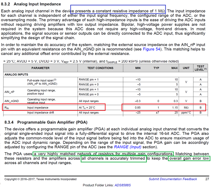
1. For the input impedance descriped in d/s, this is important as it could introduce system gain error. the spec. said input impedance has +/-15% vairsion around 1Mohms, but the PGA/input impedance section also said this input impedance is one stable and trimmed to match the system gain error. So my quesion is that Rin impedance is accurate or not? if NOT, I need compenste this error in my system design, correct? if the Rin is trimmed inside chip, how about the accuracy and its temperature drift?  btw, how about PGA's feedback resistor accuracy?

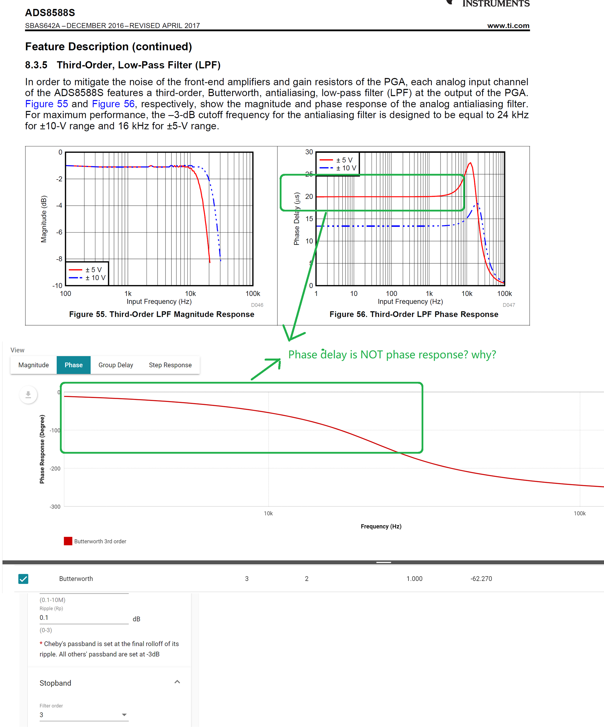
2.  For the "Third-Order, Low-Pass Filter (LPF)", can I disable it if I don't need it? also, if can I set this as second-order Low pass filter and fine tune the 3db bandwidth? it sounds the phase delay has a little longer for me for this 3rd-order LPF inside.

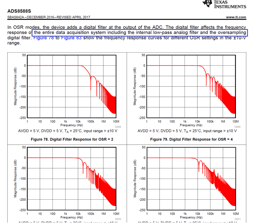
3. For OS operation mode, how to understand " The digital filter affects the frequency response of the entire data acquisition system including the internal low-pass analog filter and the oversampling digital filter."? as I understand, the LPF is independent on the oversampling digital filter, so how this digital filter would impact the frequency response of both LPF and digital filter from oversampling (averaging digital filger)?

thanks for clarifying my confusion.

Regards,

Feng

  • Hi Feng,

    Thank you for providing the details about your questions.

    1. The input impedance, Rin, has been characterized and specified in the table as you showed above, the typical value is 1Mohm and the variation is between 0.85 to 1.15Mohm. Also, you can see the temp drift specification in the same table. The actual gain error depends on Rin and also your the resistance in your front-end circuity. If the error can not meet your requirement, you will have to do a calibration on system level.

    2. The internal LPF can not be disabled or bypassed. The 3-dB BW of the LPF depends on the input range you configured on RANGE pin (24kHz for +/-10V range and 16kHz for +/-5Hz range).

    3. It's true that the internal LPF is independent from the digital filter. However, both filters should be considered for the whole signal chain when converting an analog signal. The combination of both filters determines the maximum input signal frequency. The analog LPF has a constant BW and frequency response once the input range is determined, however the digital filter has different frequency responses with different OSR values. When the OSR is small, the BW is dominated by the LPF. When the OSR is larger, the BW is dominated by the digital filter.

    I hope these can help you understand,

    Best regards,

    Dale

  • Thank Dale. For the 3rd issue, Figure78~Figure83 are the combine result from both LPF and OS filter?

    btw, do you have idea on how to calibrate the error from external resistor and internal resistor? how about the PGA feedback resistor accuracy, may i need take care of it as well?

    Feng

  • Hi Feng,

    These are figures of frequency response for digital filter.

    For calibration, see the video Precision Labs ADCs - 5.2 Understanding and Calibrating the Offset and Gain for ADC Systems.

    You only need to care about the accuracy and drift of 1Mohm input impedance which have been specified in the data sheet, not other resistors.

    Best regards,

    Dale

  • Got it. so we must have gain error calibration in our system to compensate the 1Mohms +/-15% error, correct?

    Thanks.

    Feng

  • Hi Feng,

    It's up to you and depends on your system's requirement.

    Regards,

    Dale

  • Hi Dale, thank you for your help. I have one more question, can you please help me understand the phase delay of ASD8858S LPF as attached? As we know the Butterworth filter has phase-freq. response curve as attached as well, they are different, how to understand ADS8858S's LPF? thanks.

    regards,

    Feng

  • Hi Feng,

    The phase response tells us the phase shift in angular between the input and output of the filter. However, it can be thought of as a time delay as well, the amount of time delay for a given frequency can be found to be the frequency derivative of the phase response, delay = dφ (ω) /dω. 

    Here is a simple conversion for your reference:

    • Assume your signal is 1kHz sinusoidal wave, so one period is 1ms and 360°.
    • According to the figure 56 in the datasheet, the phase delay for +/-5V range is 20us at 1kHz frequency.
    • so the phase shift is (20us/1ms)*360=7.2°.

    I hope this helps you understand.

    Best regards,

    Dale

  • Thank Dale. So I can unerstand it as time delay NOT phase delay. can it be same as group delay?

    Feng

  • Hi Feng,

    Group delay is constant and same as phase delay for linear phase filters. However, this filter is not a linear phase filter.

    Best Regards,

    Dale