


Hi,
I have an ADS1299 board with a 3.3v line and a 0-5v biasing line. I believe I followed the datasheet religiously and I had this result:
the GNDA/GND nets are two separate ground planes for 3.3 and 5 that are jumped.
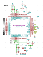
Now, when we boot our board and talk with the chip over SPI, we get valid "test" data and stream 0V from the device, as expected. But we don't see our biasing capacitors fill to the correct voltages like we do on the OpenBCI board we have. We don't understand if our bias circuit is fundamentally wrong or we just have a bad ADS chip/ESD issue. I've ohmed out all the connections and they match the schematic exactly.
Should we just replace the chip? Or is the schematic fundamentally wrong?
