This thread has been locked.

If you have a related question, please click the "Ask a related question" button in the top right corner. The newly created question will be automatically linked to this question.

DAC8760: Latch Signal in Daisy Chain

Part Number: DAC8760
Other Parts Discussed in Thread: DAC7750

Hi,

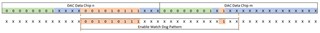
we built a board with two DAC8760 connected in DaisyChain to a Kinetis K22 SPI. Both chips have their own ChipSelect signal.

When adressing the first DAC8760 in the DaisyChain everthing seems to work fine.

Trying to access the second device gives unexpected behaviour in both devices.

It kinda seems that the first DAC8760 is interpreting some of the data after 24 clock cycles although there is no rising edge of the corresponding ChipSelect signal. Same problem without a solution: https://e2e.ti.com/support/data-converters-group/data-converters/f/data-converters-forum/471368/dac7750---is-it-possible-for-the-device-to-take-action-on-its-input-shift-register-contents-without-seeing-a-rising-edge-on-latch-if-a-particular-pattern-is-present-on-din-and-sclk

The datasheet is not very accurat on this topic and several forum posts in the E2E forum show an unexpected and not SPI standard behaviour. Unfortunately there is no clear solution or answer on how the latching in daisy chain mode works.

Questions:

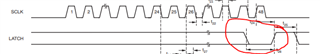
  1. can the ChipSelect signal be low during all transmission with a rising edge at the last bit latching the data? or will the chip latch the data in after 24 bits anyways? the datasheet kinda assumes a dontcare for the 0-23 bits.
  2. the DAC7750/DAC8760 sample code shows a manual toggle (high-low-high) of the latch pin after transmission of all bits from high to low to high. is this the only way to latch data input? this is the opposite of the dontcare in the datasheet.
  3. when transmitting 48 bits in DaisyChain (DCEN = 1) the first device seems to latch in data when ChipSelect is low and has no rising edge. this can be read from many forum posts as well. is this normal behaviour?
  • Jörn,

    First, I do not recommend using Daisy Chain mode. It can be difficult to get working, and because of some of the problems that you pointed out in the E2E post that you've found. It is the same reason that is discussed in section 8.3.10.1 and 8.3.11.1 with the device interacting with the SPI. With certain bit inputs with the data shown in those sections, the device can erroneously activate the watchdog timer alarm or the CRC alarm. In the end, it's easier to use the device with a controller that can handle two independent sets of SPI, or having parallel SPI lines with separate /CS selections and a gated SCLK.

    Going to your questions:

    1. To be clear, the signal is really LATCH. The signal can be low during the transmission and the rising edge will latch in the data. As mentioned before, certain bit inputs may trigger the erroneous watchdog timer alarm or the CRC alarm.

    2. I'm not sure what you mean by the high-low-high pattern. Are you talking about the LATCH signal in the timing diagram (as below)?

    In this case the LATCH rising edge is the signal that clocks the data into the device.

    3. As I mentioned before, I do not recommend the daisy chain mode because of the problems as discussed in 8.3.10.1 and 8.3.11.1. Regardless, both device latch data when the LATCH goes high. In this mode the SDO is not a straight pass through of the DIN data. The SDO is a 24-bit delayed version of the DIN. Therefore when the LATCH signal comes, the two different values are received by the devices.

    I'm not sure if I've covered everything so if you have any other question please post back.


    Joseph Wu

  • Hi Joseph and thank you for your detailed answer.

    I will assume this interpretation of "SPI" by TI is a FAIL which makes me think the device should be replaced by another brand that can handle SPI as it should be.

    Anyways:

    Regarding 1: OK, so LATCH can be like any SPI LATCH/CS signal generated by every microcontroller (i never saw a SPI controller in any microchip doing CS/LATCH as described here).
    The enable watchdog message from Table 4 page 32 has a lot of dont cares. so any bit sequence of 0b 0010 1011 1XXX XXX XXX X1XX will trigger the interface. in other words it is only safe to not send those patterns ever out to any device in the chain. as this is a DAC, how to avoid such bit patterns? and maybe there is an EEPROM or similar in the chain. this is so hilarious Slight smile (i assume it is a bug in the hardware sold as a feature).

    Regarding 2: yeah, got it.

    Regarding 3: this is normal behaviour of SPI i think. both devices have 24 bit registers, so i have to clock 48 bits with both messages (one for device a and one for device b) and after 48 clocks the latch for the devices. but i have to not send 0b 0010 1011 1XXX XXX XXX X1XX because it will make the device latch in data...

    Two last questions:

    - if i only have DACx760 devices on my SPI, is it assured that 0b 0010 1011 1XXX XXX XXX X1XX will only occur by purpose on the bus and not by chance due to the digital to analog data?

    - if a DACx760 sees a 0b 0010 1011 1XXX XXX XXX X1XX on the bus that triggers its automatic SPI latching, will it continue to clock through the remaining data and latching it in as usual? so if ALARM pin is not used and watchdog functionality is ignored, may it work anyways?

  • Joe is taking a look at this now and should have a response to the comments tomorrow.

  • Jörn,


    I'm not sure if I understand the first question. If you're using just the DACx760, you're only using a specific set of commands, so you wouldn't send the 0b 0010 1011 1XXX XXX XXX X1XX unless you were to purposefully enter this as a command.

    If the DAC sees the 0b 0010 1011 1XXX XXX XXX X1XX, then it should continue to operate. However, depending on how the part is used, there may still be issues.

    The problem comes from a digital circuit within the device. Normally you would think that the device can receive DATA from SDI/SCLK and then when the LATCH goes high, the device would take the last 24 bits (32 if CRC is enabled) and execute the command. However, the digital section looks for specific patterns of incoming data. One issue is that one bit pattern may trigger the watchdog timer and cause the device to set the ALARM. This could be a problem when there are SDI/SCLK on the pin, and there are multiple devices on an SPI bus (like using LATCH as a /CS). With other communications going on to other devices, this could cause a problem for the DACx760 (which is basically considered as unselected).

    This may also be a problem with chain mode, where you have more communication going on before the device is set to be latched. There may be many communications on SDI/SCLK depending on the number of devices in the chain. In this case, we've seen where the CRC was enabled, and by sending an unintended bit pattern the CRC was turned off.

    The reasons above were why sections 8.3.10.1 and 8.3.11.1 were added to the datasheet. Using these descriptions, you could avoid specific bit patterns going to the device. I would need to consult with design to verify more of the details if you wanted a fuller explanation.

    It has been in the works for several months, but a new version of the datasheet is now available. At this point, we've removed the daisy chain mode from the datasheet and added some clarification for other sections of the device. I didn't mention it earlier because I didn't know the exact timing of when it would be released.

    Let me know if you need some more details about these issues and I can follow up with design.


    Joseph Wu

  • Hi Joseph

    thank you very much for this really detailed explanation!

    What i ment by my first point is that the "Enable Watchdog Timer Digital Interface Pattern" will be processed by the DACx760 even without a LATCH signal as you and the old version of the datasheet explained in 8.3.10.1.

    My point now is that i can fit this pattern in any communication, even if my chain only consists of DACx760 devices.

    I made an illustration to show what i mean:

    When i am sending DAC Data the pattern can occur depending on the data i want to put out. And that will enable the WatchDog by mistake.

    This will only work if the device is the only device on an SPI bus and the internal mechanism searching for this pattern is reset if a rising edge on the LATCH occurs. Am i wrong on that?

    We will now change our design to one SPI for each DAC.

    Thank you for your effort!

    Greetings Jörn

  • Jörn,


    I'll need to get back to you on this one. The scenario you describe with the pattern seen with daisy chained devices concerns me as well. My thought was that the pattern is still seen because there is no latch between the two data frames. Even if the devices were both DACx760 devices, I thought this would still be a problem.

    I did have a short conversation with one of the design engineers that reviewed this problem and he was pretty sure that you could still get the daisy chain to work. However, the communications would need to be exact and controlled.

    As I mentioned, I'll get back to you soon. In the mean time, read through the new version of the datasheet and see if you have any questions about it.


    Joseph Wu

  • Hey,

    we came to the conclusion that this device is not safe to be implemented in daisy chain and we will change our design and put every DAC on a seperate SPI bus from the microcontroller.

    The only question that remains is if the mechanism looking for that specific pattern will start counting from 0 after a rising latch, because the above pattern with two DAC Data send to ONE device can still occur. But with only one device we have easier control over the data, we could send a NOP every second transmission for example.

    Greetings