This thread has been locked.

If you have a related question, please click the "Ask a related question" button in the top right corner. The newly created question will be automatically linked to this question.

AMC1306M25: Difference for Vcm and CMRR between AMC1204 and AMC1306

Part Number: AMC1306M25
Other Parts Discussed in Thread: AMC1204,

Dear Teams,

According to datasheet, the Vcm for AMC1306M25 (0.16 to AVDD-2.1V) is narrow than AMC1204's Vcm (-0.16 to AVDD). Also, the CMRR for AMC1306 95db is smaller than AMC1204's 108/114db.Could I say it is harder for customer to do PCB layout to avoid interference and noise when they used AMC1306M25 than AMC1204 because of narrow Vcm and lower CMRR value? Alternatively, could I say AMC1204 has better anti-noise and anti-interference performance than AMC1306?

Thanks!

Dylan

  • Hi Dylan,

    There are some pretty significant structural differences between the AMC1204 and the AMC1306M25.  Please review the two datasheets - Figure 44 for the AMC1204 and the Functional Block Diagram for the AMC1306 (page 21).  The AMC1204 is a first generation isolation device with a switched capacitor input while the AMC1306 has more of a traditional differential input structure.  The AMC1306 also has fail-safe features that are not on the AMC1204 - this is the reason for the Vcm differences.  The other major difference is in the isolation ratings, 3kV for the AMC1204 and 5kV for the AMC1306.  Careful PCB layout is critical for both parts, so I would place isolation requirements above CMRR or Vcm concerns.  What are your needs, basic or reinforced isolation?

  • Hi Tom,

    Please forgive my silly questions here. I did checked the DS for AMC1204&AMC1306M25 before. Just now I have take a look on the fail-safe feature for AMC1306 as well. But, I am still confusing what is the relationship between fail-safe feature and Vcm because I think fail-safe function is only to ensure the output voltage keeps at clear logic level once there has no AVDD. Could you help explain more about fail-safe and Vcm?

    Based on customer design, they are OK with basic isolation and its isolation rating 3kV. They switch from AMC1204 to AMC1306 simply due to supply shortage.

    Could I get more insights on the difference between the switched capacitor input structure and traditional differential input structure? If you think it is confidential, how about sending an email to me?

    Thanks!

    Dylan

  • Hi Dylan,

    The AMC1306M25 has missing AVdd fault and Vcm fault detection (see the resistor divider in the block diagram). 

    Beyond what is in the datasheet, there is not much more that I can discuss here on the forum, but you can look at the difference in bias currents between the two devices.  That delta is due to the difference in input structures.  The differences in input impedance is also related to the input structures - the AMC1204 input impedance is dynamic, and based on the clock speed and S/H cap as shown in Figure 44.  The difference in input impedance between the two parts has implications when either device is used in a voltage monitoring application.  The R3' described in the AMC1306 datasheet would not be needed with the AMC1204 .  

  • Hi Dylan,Hi Tom

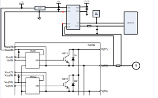
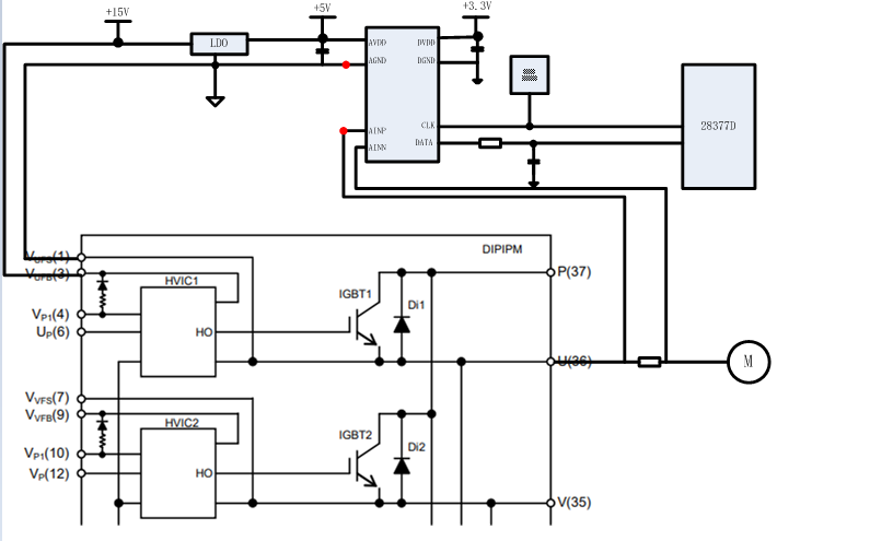
    My  company  is Dylan’s customer.We found that if the pcb Layout of amc1204 is used in amc1306, ADC sampling will be abnormal.In the figure below, we establish equipotential connection between pin AGND and pin AINP of amc1204 through IPM module. We find that all functions are normal.

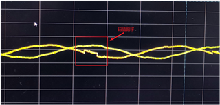
    But we found that if the pcblayout of amc1204 is used in amc1306, sampling exceptions will be caused.

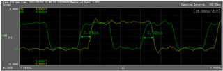
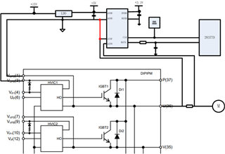
    At first, we suspected that the timing of amc1306 led to the steup  time and holding time not meeting the requirements of 28377.However, we found that this has a great relationship with PCB layout. We connect AGND and ainp AINP directly at a short distance. All functions are normal. At present, we still use the rising edge synchronous sampling method of 28377.

    We expect to know from the principle why the two chips have such differences.

  • Hi Hui,

    The AMC1204 and AMC1306 have different timings as you've noted.  Is the picture above from an AMC1306 or from AMC1204?

  • And can you show us what the AMC1204 look like?

  • Do you expect to see the oscilloscope waveform or circuit schematic diagram of amc1204? The following figure is the circuit schematic diagram of amc1204.The waveform collected by amc1204 is continuous.

  • Hi Hui,

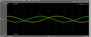
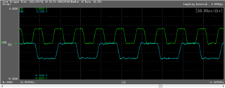
    I was hoping to see the data and clock waveforms too.  So, if I understand correctly, when using the AMC1306 - if you tie VINp and AGND together directly at the chip, you get a continuous waveform (no jumps) like the picture above.  However, if you leave the AGND connection through the IGBT module (which works fine for the AMC1204), you can see discontinuities in the current waveforms like you show in the posting of 12DEC, is that right?

  • Your understanding is correct about when using the AMC1306 - if you tie VINp and AGND together directly at the chip, you get a continuous waveform (no jumps) like the picture above.  However, if you leave the AGND connection through the IGBT module (which works fine for the AMC1204).

  • Hi Hui,

    The AMC1204 does not have the same Vcm fail-safe feature that is found in the AMC1306.  With the AGND connection going through the IGBT module, the trace inductance is going to be much larger than it is with a direct connection to the shunt.  I suspect the discontinuities you see are due to bit errors in the AMC1306 output with the long trace going back through the IGBT module.  Have you tried the same direct connection with the AMC1204?  I'm curious to know if you see any difference in the overall performance of your drive with the AMC1204 connected the same way as the AMC1306.

  • Have you tried the same direct connection with the AMC1204?YES,

    For a long time, the agnd of amc1204 was connected with the AINP pin inside the IGBT module. The performance of the drive is normal. Exceptions were not found until amc1306 was tried.

  • Hi Hui,

    Have you shorted the AMC1204 pins 2 to 4 in the same manor as you have with the AMC1306 and verified performance (as opposed to shorting through the IGBT module)?  This is the generally recommended way to use both devices - you can review the layout recommendations where we show AGND being tied directly to the shunt.  More often than not, it is easier to short AINn to AGND but it works just as well shorting AINp to AGND.

  • 1. Amc1204 needs to connect agnd short to the PCB layout of shunt resistor. Please give me the screenshot of relevant chapters of datasheet
    2. The purpose of initiating this issue is to find out the difference between amc1204 and amc1306 in which index leads to their different characteristics on this issue. And you've been avoiding answering this topic. Please answer positively.

  • Hi Hui,

    1.) Both the AMC1204 and the AMC1306 should have the AGND (pin 4) of the device connected to the shunt.  I don't believe that is specifically spelled out in the AMC1204 datasheet, but that is the general intention depicted in Figure 50 of the datasheet.  

    2.) I have told you starting at the beginning of this conversation the differences between the AMC1204 and the AMC1306.  The AMC1204 was one of our first generation isolated modulators.  Besides the fact that data is driven on different edges of the clock for the AMC1204 and AMC1306, the AMC1306 has fail-safe features the AMC1204 does not have.  The AMC1204 has a switched capacitor input structure, the AMC1306 is resistive.  They are different designs in general.  I have not avoided answering your questions, I'm trying to help you find a way to use either device interchangeably.  

    It is difficult to try and help you fully debug the issue without seeing the full schematic, layout, more screen shots of the data as it is received by the filter module, etc.  In our last conversation, I asked you if the same short circuit that you need for the AMC1306 works just as well for the AMC1204.  If it does, that 'fix' should allow either device to work in your system.