This thread has been locked.

If you have a related question, please click the "Ask a related question" button in the top right corner. The newly created question will be automatically linked to this question.

ADS1298 ECG data read problem only 7FFFFF

Other Parts Discussed in Thread: ADS1298

Hello,

i use the ADS1298ECG-FE with the ATMEL SAM3U-EK and i have a problem to read the ECG data. I can read and write the register with my SPI but when i will read the channel data i only get 7FFFFF. I only use one channel and the other seven are powered down. So i connect the RA (channel 1) with a ECG simulator but nothing changes. I always get 7FFFFF the Vref voltage explained on page 27 of the datasheet. When the DRDY pin goes low i read out the 27 byte (3 byte status register and 8 channel). I get the following bytes:

1100 0000 0000 0000 0000 0001 status register

0111 1111 1111 1111 1111 1111 channel 1

7 times 0000 0000 0000 0000 0000 0000 channel 2 - channel 8

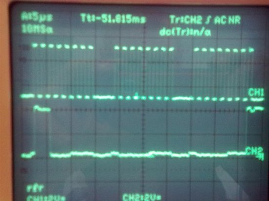
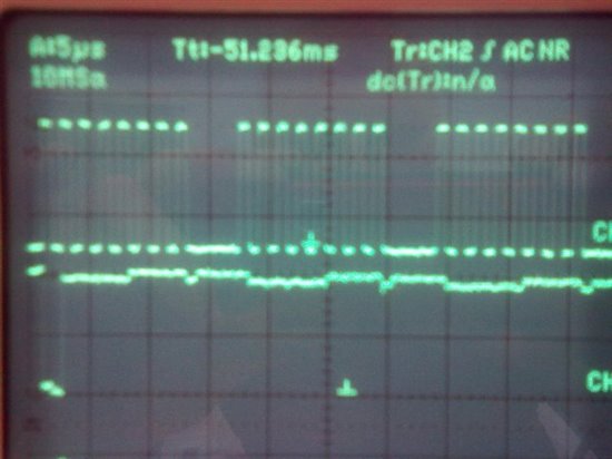
So the `0` for channel 2 -channel 8 are OK because i have them powered down but the channel 1 doesn't change. I´m using the continuous mode and wait a certain time and then i send the SDATAC and STOP command with my SPI. And during this time the data of channel 1 is always 7FFFFF. I use for the analog voltage 3.3 V and for the digital 2.5 V and the VREFP is set to 2.4 V in config3 register. I hope my power management is OK. The JP24 is between 2-3 and the JP2 between 1-2. I don´t know what i´m doing wrong because my SPI works and i get the data which i see on the oscilloscope. I have insert two pictures. You can see the SCLK and the DOUT of the ADS1298. The first picture are the first three byte (the status register) and the second picture is the next three byte (channel 1). I hope you can help me and tell me what i´m doing wrong.


Best Regards

Eckart


  • Hi Eckart,

    Welcome to the e2e forum!  For the ADS1298 board, having JP2 shorted pins 1-2 and JP24 shorted pins 2-3 is going to give you a bipolar +/-2.5 (5V) analog supply.  For a unipolar 3V analog rail, the shunts should be shorting JP24 pins 1-2 and JP2 pins 2-3.  This might be part of your problem.  Do you get proper data from CH1 using one of the test modes or when reading temperature for instance?  Also, just an FYI really, but if channels 2-8 are powered down, you do not need to read them - this might save you a little overhead in your code. 

  • Hello Tom,

    thank you for your fast answer. I have found the problem. The ECG cable between my ECG simulator and the ADS1298-FE was damaged. I changed it and now it works. But i have two new questions. When the channel 1 is set to the temperature sensor and i want to read out the temperature. How many byte must i get and what does this mean in voltage? How can i convert it to voltage to put the value into the equation of page 20 of the datasheet? And my second question is how to convert the data of channel 1 when it is set to a normal electrode into voltage. For example i get a value of FFFB7C and i can read the table of page 27 of the datasheet where FFFFFF = –VREF/(2^23 – 1) (-2.4V/(2^23-1) =-2.86E-7 V). What is FFFB7C convert to voltage? Or when i get a value of the channel 1 of three byte like 002F6E. What does it convert to voltage?

    Best Regards

    Eckart

  • Hello Eckart,

    See the spreadsheet below for reference. Essentially, these values are broken down into 2 categories, and are handled slightly different.

    1) If the value is (+), positive - meaning first bit is a '0' [7FFFFF - > 7 = 0111 ... -> first bit is '0' -> value is (+)], then convert to DEC. Then multiply by the LSB weight [Vref/ (2^23 -1)].

    Ex: Assuming 2.4Vref => 002F6E : B2C -> DEC = 12142.

    => LSB weight = 2.4V / (2^23 -1) = 2.86E-7.  

    => 12142 * 2.86E-7 = 3.47E-3V.

    2) If the value is (-), negative - first bit as '1', then convert to DEC. At this point, you must compensate for the 2s complement. The easiest way to do this is to subtract the full-scale bit range (2^24 = 16777216) from that converted DEC value. Then, multiply by the LSB weight.

    Ex: Again assuming 2.4Vref => FFFB7C : B2C -> DEC = 16776060

    => compensation = 16776060 - 16777216 = -1156 [note: the (-) makes sense, since it is a negative voltage]

    => LSB weight = 2.86E-7

    => -1156 * 2.86E-7 = -3.31E-4V.

    B2C B2C->DEC DEC->BIPOLAR 2.400V 4.000V
    7FFFFF 8388607 8388607 2.40E+00 4.00E+00
    3FFFFF 4194303 4194303 1.20E+00 2.00E+00
    10 16 16 4.58E-06 7.63E-06
    1 1 1 2.86E-07 4.77E-07
    0 0 0 0.00E+00 0.00E+00
    FFFFFF 16777215 -1 -2.86E-07 -4.77E-07
    FFFFF0 16777200 -16 -4.58E-06 -7.63E-06
    FFFB7C 16776060 -1156 -3.31E-04 -5.51E-04
    FFFB7B 16776059 -1157 -3.31E-04 -5.52E-04
    FFFB7D 16776061 -1155 -3.30E-04 -5.51E-04
    FFFB7E 16776062 -1154 -3.30E-04 -5.50E-04
    800000 8388608 -8388608 -2.40E+00 -4.00E+00

    Hopefully this helps clarify.

    Regards,

    Michael

  • Hello Michael,

    this is very helpfully but what is with the gain? I have saved the .xls files of your ADS1298ECG-FE software for the code and the associated volts and tried your example equation. So it wasn't the correct result but i divide it through the gain and this was the correct result. I have a example of this .xls files. This are the first three values of a measurement and one positive measurement.


    CH1

    Volts                               Codes

    -6,92E-05 V                     FFFFFFFFFFFFFA55

    -8,67E-05 V                     FFFFFFFFFFFFF8E6

    -7,97E-05 V                     FFFFFFFFFFFFF978

           :                                                  :

    2,04E-04                                                     10C0


    example 1:  FFFA55->16775765 dec      -> 16775765 - 16777216 = -1451 * 2,86E-07 V = -4,15E-04 V

    -4,15E-04 V / 6 (gain)= -6,92E-05 V

    example 2: 10C0->4288 dec                   ->4288 * 2,86E-07 V =1,23E-03 V

    1,23E-03 V / 6 = 2,04E-04 V

    So if i divide through the gain i get the correct result. Is this Ok? Thank you.

    Best Regards

    Eckart


  • Hi Eckart,

    I apologize about the time it took to get to this.

    This is because you have to account for the gain when converting back to volts from codes.  Table 8 in the datasheet shows note 1, which states that we assume a gain of 1. So, you'd have to divide that out when you have a different gain. 

    Regards,

    Michael

  • Hi Michael,

    thank you for your answer and for solving the problem. My ADS1298 works now fine with my SAM3U-EK and i can see the ECG on my display in two or one channel mode.


    Best Regards

    Eckart

  • Hi Eckart,

    Awesome, happy everything works for you now!

    Regards,

    Michael