This thread has been locked.

If you have a related question, please click the "Ask a related question" button in the top right corner. The newly created question will be automatically linked to this question.

DAC8760: 0V output can not be calibrated.

Part Number: DAC8760

Hello guys,

One of my customers is evaluating DAC8760 for their new products.

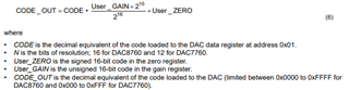
They tried to calibrate DAC8760 VOUT by DAC gain calibration and zero calibration register as the follows.

They could calibrate 10V and 5V output but couldn't calibrate 0V output. 

Do you know any way to calibrate 0V output voltage?

[Before user calibration]

DAC gain calibration register = 0x8000

DAC zero calibration register = 0x0000

0V output =0.0049V

5V output =5.0051V

10V output =10.0046V

[After user calibration]

DAC gain calibration register = 0x8003

DAC zero calibration register = 0xFFE2

0V output =0.0047V

5V output =5.0002V

10V output =9.9998V

[DAC8760 power supply]

AVDD=+24V

DVDD=+3.3V

GND=0V

AVSS=-3.3V

Thermal Pad=-3.3V

Could you please give me your reply?

Best regards,

Kazuya.

  • Kazuya-san,


    It is not clear to me how your customer got the measurements and calculated the gain and offset calibration register values. Can you go through their process and show me their calculations?

    I think part of the problem may be that they are using the ends of the codes to calculate the gain error and that there are limits at the edges after the user calibration. While using the 0000h code to calculate the offset value might work, I would use certainly use values off the edge to calculate the gain error. Instead of using 0000h and FFFFh for the gain, use 0200h and FE00h and their output values to calculate the gain calibration. Then you can apply the offset calibration using the the 0200h value based on the ideal and measured output.

    When they do verify the output voltage, they should measure several points. I would choose 9 points from 0000h to FFFFh (0000h, 2000h, 4000h, etc). Note that because the offset is a straight subtraction with the offset calibraton value, so the slope adjustment may be limited on one side of the curve. Instead of using the exact 0000h or FFFFh at the very ends, you can use the 0200h and FE00h values again.

    I think they should get an accurate value with that method. Have them try that calibration you can post back their results.


    Joseph Wu

  • Hello Joseph,

    Thank you very much for your reply.

    I confirmed them how they calculated the gain and zero calibration code.

    They referred 8.3.11 User Calibration section on page 34 of DAC8760 datasheet (Ver.SBAS528D) for the calibration.

    They will try to calibrate the output with the method you tell us.

    Also they want to ask you the following question. Could you please give me your reply?

    [Questions]

    10V output has been calibrated with -0.2mV error, 5V output has been calibrated with +0.2mV error. 

    But 0V output has been calibrated with +4.7mV error.

    We think +0.6mV is reasonable number and +4.7mV is larger than we expected.

    Is this calibration characteristics normal performance of this device ?

    Is this linearity normal characteristics of this device?

    We used the circuit of Figure 9-2. VOUT and IOUT Tied Together to One Pin and IOUT is buffered

    with the circuit of Figure 8-6. Boost Mode Configuration.

    Does these circuit affect output voltage linearity around 0V output?

    Your reply would be much appreciated.

    Thank you again and best regards,

    Kazuya.    

  • Kazuya-san,


    I was hoping that they would show their calculations (at least explain the method) as how they got the value for calibration values. Also, the method of setting several values and measuring the output would have shown if there is some sort of non-linearity in the DAC output. If the DAC does have some problem with 0V out, then the DAC code near 0000h would show a non-linearity, while the output for the remaining codes would have been linear.

    If the supply is unipolar (0V to 24V for AVSS to AVDD), then there may be a non-linearity problem with zero code output because the buffered voltage output wouldn't be able to reach 0V. However, the customer appears to have the supplies set to a bipolar value (-3V to 24V for AVSS to AVDD). Because of this, I would have expected the zero code error to be small or zero.

    Again, I would like them to try to determine the calibration values as I had mentioned. Use DAC codes that are near zero scale and near positive full scale, and then take the data at even intervals through the full scale range. This way, we can determine where the DAC outputs are non-linear.


    Joseph Wu

  • Hello Joseph,

    Thank you very much for your reply.

    I confirmed their procedure for calculation of the calibration data. It is the following.

    1. Measure Initial VOUT at 0V(Vo_Int_0V) and 10V code(Vo_Int_10V) with DAC Gain and DAC Zero Calibration registers are default value.

        Their measured result

        0.0050V at 0V code, 10.0046V at 10V code, the difference voltage(Vd) is 9.9996V 

    2. Calculate the initial gain(Gint)

         Their calculated result

         Gint = 10/Vd = 1.000040002

    3. Calculate User GAIN

        User GAIN = (65536*Gint) - 32768 = 32771 = 0x8003

    4. Calculate the initial zero shift(ZSint)

        ZSint = 10-(Vo_Int_10V*Gint) = -0050002

    5. Calculate User ZERO

        User ZERO = (ZSint/11)*65536 = -30 =FFFFFFFFE2 =0xFFE2 (lower 4digits)

    Could you please check this procedure and please give me your comment or advice?

    Thank you again and best regards,

    Kazuya. 

  • Kazuya-san,


    First, I think that your customer has accidentally connected GND to AVSS. If the AVSS and GND are both at 0V, then the zero code error is going to be several mV. If your customer is using the DAC8760EVM, then they need to apply the negative supply from GND to AVSS. However, they also need to remove the jumper on JP1. This jumper connects AVSS and AVDD. If they are using the EVM, they should make sure they check the schematic. I've run this test with +12V for AVDD and -3V for AVSS and my zero code error (when my DAC code is 0000h) is about +0.00009V. This is less than 1LSB.

    In the datasheet this is the calibration equation:

    When there no calibration used, the user sets the CODE, and that code is used to set DAC.

    However, when calibration is used, the user sets a CODE. However this CODE is modified to get CODE_OUT. CODE_OUT is the value used to control the DAC output. This calibration is a digital calibration and CODE_OUT is limited by the 2^16-1 range. That means when you enter in a CODE, the output for CODE_OUT cannot be lower than 0000, and cannot be greater than FFFF.

    For example, if you have a large positive offset then you would want to subtract values to lower the output of the DAC. In your customer's example they want to subtract 30 codes. When the user enters in CODE, the DAC8760, the offset calibration subtract 30 from CODE. If CODE is already at 0000h, the CODE_OUT cannot go below 0000 and the DAC output stays at 0000.

    Also, if the gain error is less than zero (where the output in the 10V range is just smaller than 10V), then the output may not reach 10V. In my example, I have basically a 0V offset, so my offset calibration is 0000h. However, I need a positive gain calibration to try to make the output signal larger. When I enter in FFFF, I get 9.99412V out.

    When I set the gain calibration to 8027h, I enter in the CODE and the device tries to multiply by 1.00059 to increase the gain. This would make the CODE_OUT 10026h to get the correct output. However, CODE_OUT is still limited to FFFFh, so the output still remains at 9.99412V when I set the CODE to FFFF.

    The output of the device is still linear, but will still be limited by the range of the DAC (without calibration). As I mentioned in a previous post, they should measure the output and check the gain error/offset and linearity at a range just higher than 0V out and just lower than 10V out.

    Attached is a spreadsheet for the DAC with different DAC codes (not all codes). The offset is basically zero, and without calibration I have a linear output. If I set the calibration values, the offset is still basically zero, but my gain calibration slightly increases the output. As the CODE is increased, I get to a point where CODE isn't yet at FFFF, but CODE_OUT has reached it and the output cannot be increased. This causes a large non-linearity at the edge of the range when I use the full endpoint range.

    Instead of finding the endpoint non-linearity, I use 100h and FF00h as the start and end codes. This removes the problem if the offset is positive or if the gain error is negative. Recalculating the INL, the non-linearity is very small. The spreadsheet is at the end of the post.


    Joseph Wu

    INL.xlsx

  • Hello Joseph,

    Thank you very much for deep supports and actual measuring.

    The customer and me could understand your explanation well.

    Thank you very much again and best regards,

    Kazuya.