This thread has been locked.

If you have a related question, please click the "Ask a related question" button in the top right corner. The newly created question will be automatically linked to this question.

TSC2003: Touchscreen position falsely reported

Part Number: TSC2003

I have a DMC analog resistive touchscreen interfacing with a TSC2003 via the traditional 4-wire interface.  A touch will result in the TSC2003 generating an interrupt.  The interrupt handler subsequently wakes a touchscreen task which is responsible for retrieving touch coordinates and passing them to the application layer for processing.

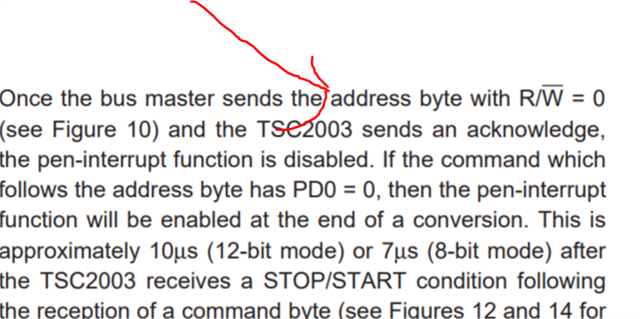
The touchscreen task is table driven.  Each table entry identifies the function to perform (i.e., read).  There is a one (1) millisecond delay between reads.  Once all functions have been performed, the task goes back to sleep.  All reads are performed in 12-bit mode.  X/Y/Z drivers are turned on prior to reading X/Y/Z coordinates.  PD1-PD0 in each command is set to "11" to disable the interrupt, turn the internal reference on and turn the ADC on.  The last function performed is to read VB1.  I am not concerned about the voltage reading, but use the command to set PD1-PD0 to "10" to enable the interrupt, leave the internal reference on and turn the ADC off.

The following has been observed:

  • X/Y/Z values appear in the first data byte.  D3-D0 in the second data byte are always 0x0F.
  • Values in the first data byte will occasionally be reported as 0x00 or 0xFF.
  • A "mechanical finger" is used to repeatedly touch the screen at a fixed location.  X/Y coordinates are usually within five (5) pixels of each other.  However, a "flyer" will get reported during testing that is no where near the fixed press location.

Our application requires that touches be accurately reported.  "Flyers" are unacceptable.

I've tried reading X/Y/Z a second time (i.e., debouncing).  I discard any readings where the X/Y measurements are 0x00/0xFF or the difference between the two readings is 10 pixels or greater.  This has greatly eliminated false readings.  However, I still run into instances where a flyer occurs with both sets of measurements appearing as valid touches.

Questions:

  • The TSC2003 lists the sampling dynamics throughput rate as 50 ksps (e.g., 0.00002 seconds).  Are there any timing requirements on how quickly measurements must be taken following the interrupt?  I am obviously limited by the speed of the I2C bus and my self imposed millisecond delay between reads.
  • Once the X/Y/Z drivers are activated, are they ever turned off?
  • Could my reading of VB1 be affecting the measurements of the next interrupt.  Moving the setting of PD1-PD0 to "10" to the second Z measurement didn't help.
  • I am not concerned about conserving power.  My understanding is that the internal reference is only needed for battery and aux input measurements.  Are X/Y/Z measurements affected by the presence/absence of the internal reference voltage?
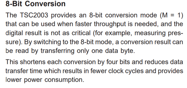
  • I have implemented pressure measurement using the second equation as it only requires X, Y and Z1 measurements.  My mechanical finger exerts a fairly consistent pressure on the screen.  However, the calculated value of RTOUCH varies greatly as the finger is moved to various parts of the touchscreen.  Could this be affected by D3-D0 always being 0x0F?  When I change to 8-bit mode, the measurements do not change.  Does the 4096 constant get changed to 256?

I've read the datasheet several times.  This shouldn't be all that hard.  I must be overlooking something simple.

Thanks in advance for everyone's time and trouble.

  • Do you have any external capacitors  mounted on the X Y pins. If so You should remove them to do the test to

    see if you get any improvement .

    Are you using the evm or have you made your own design.? Can you send a copy of the schematic of this section?

    You can try the following as a test: We try activating only the X measurement without interrupt functionality to see if we get stable value.

    Start

    Device Address 0x90

    Control Byte      0xC4

    Stop

    Wait 20us

    Start

    Address 0x91

    Read databyte  2

    Read databyte  1

    Stop

    Repeat this every 20 milliseconds.

    Check x data as you move the finger over the screen. Is it consistent stable without any aberation.

    You can also watch on a CRO. Place x+x- and Y+ on CRO. When X+ is high and X- is 0, Y+ will have the X value

    as a voltage between 0 to 3.3v.

    Perhaps this test will give a hint about what may be wrong with the setup.

  • Our hardware design does not incorporate discreet capacitors on the 4-wire connection between the touch screen and controller.  We do, however, have EMC filters between the two which were NOT removed for this testing.

    I am running VxWorks and using its I2C driver.

    A Saleae Logic Pro 8 is monitoring I2C traffic. The SCL is running at roughly 360 KHz (i.e., near the top end of I2C fast mode). The VxWorks I2C driver can send the address and command bytes out in roughly 160 microseconds. The time between the address/measure X command and the subsequent address/read request is roughly 60 microseconds. The 2-byte read response is returned within roughly 90 microseconds of read command. A 20 millisecond delay was inserted between each "measure X" command.

    Using breakpoints to capture data or even buffering the data for later examination is not practical. I added "instrumentation" to dump values in real time to the telnet port. Each measure X command would have its response written to telnet. 25 consecutive read requests were performed followed by a 3 second delay to ensure all telnet traffic was sent. This also gave me the ability to cleanly reposition my finger on the touch screen between samples.  Here is a sample of the results:

    0002341738 - Sample 25: MEASURE_X [0x0E][0xFF]
    0002341758 - Sample 24: MEASURE_X [0x0E][0xFF]
    0002341778 - Sample 23: MEASURE_X [0x0E][0xFF]
    0002341798 - Sample 22: MEASURE_X [0x0E][0xFF]
    0002341818 - Sample 21: MEASURE_X [0x0E][0xFF]
    0002341838 - Sample 20: MEASURE_X [0x0E][0xFF]
    0002341858 - Sample 19: MEASURE_X [0x0E][0xFF]
    0002341878 - Sample 18: MEASURE_X [0x0E][0xFF]
    0002341898 - Sample 17: MEASURE_X [0x0E][0xFF]
    0002341918 - Sample 16: MEASURE_X [0x0E][0xFF]
    0002341938 - Sample 15: MEASURE_X [0x0E][0xFF]
    0002341958 - Sample 14: MEASURE_X [0x0F][0xFF]
    0002341978 - Sample 13: MEASURE_X [0x0E][0xFF]
    0002341998 - Sample 12: MEASURE_X [0x0F][0xFF]
    0002342018 - Sample 11: MEASURE_X [0x0E][0xFF]
    0002342038 - Sample 10: MEASURE_X [0x0E][0xFF]
    0002342058 - Sample 09: MEASURE_X [0x0E][0xFF]
    0002342078 - Sample 08: MEASURE_X [0x0E][0xFF]
    0002342098 - Sample 07: MEASURE_X [0x0E][0xFF]
    0002342118 - Sample 06: MEASURE_X [0x0E][0xFF]
    0002342138 - Sample 05: MEASURE_X [0x0F][0xFF]
    0002342158 - Sample 04: MEASURE_X [0x0E][0xFF]
    0002342178 - Sample 03: MEASURE_X [0x0E][0xFF]
    0002342198 - Sample 02: MEASURE_X [0x0E][0xFF]
    0002342218 - Sample 01: MEASURE_X [0x0F][0xFF]

    Note that the second byte of all reads is 0xFF.  This does not agree with my understanding of the datasheet.

    The value preceding each is an internal millisecond counter maintained by VxWorks.

    Since I am polling the screen, instantaneous single touches cannot be generated as in my interrupt version. I maintained constant pressure on the screen using either my finger tip or a stylus (i.e., a pencil). As expected, "measure X" returned values near 0x0 at the top of the screen and values near 0xFF at the bottom of the screen. I would see slight variations (e.g., +/- 0x01) in values as long as I maintained pressure at the same location.  The results are stable nonetheless.

    What I found interesting is that with no screen contact whatsoever the values would slowly gravitate towards 0x80 (i.e., the middle of the screen). If I touch the top of the screen and remove my finger, I would see the reported value start near 0x0B and over the course of several minutes gradually approach 0x80.  I have no explanation for this. This "should not" cause any issues in an interrupt driven application.

    I expanded my polling test to include Y measurements (i.e., read command 0xD4). Initially, I did not insert a delay between measure Y and measure X. I still had the 20 millisecond delay between reading each pair.

    With no screen contact, values varied wildly around the 0x80 center point unlike the earlier test. For example,

    0000070468 - Sample 01: MEASURE_Y [0x8C][0xFF] MEASURE_X [0x85][0xFF]
    0000070488 - Sample 02: MEASURE_Y [0x76][0xFF] MEASURE_X [0x8A][0xFF]
    0000070508 - Sample 03: MEASURE_Y [0x87][0xFF] MEASURE_X [0x89][0xFF]
    0000070528 - Sample 04: MEASURE_Y [0x89][0xFF] MEASURE_X [0x7E][0xFF]
    0000070548 - Sample 05: MEASURE_Y [0x81][0xFF] MEASURE_X [0x86][0xFF]
    0000070568 - Sample 06: MEASURE_Y [0x8B][0xFF] MEASURE_X [0x7C][0xFF]
    0000070588 - Sample 07: MEASURE_Y [0x86][0xFF] MEASURE_X [0x83][0xFF]
    0000070608 - Sample 08: MEASURE_Y [0x8E][0xFF] MEASURE_X [0x79][0xFF]
    0000070628 - Sample 09: MEASURE_Y [0x81][0xFF] MEASURE_X [0x85][0xFF]
    0000070648 - Sample 10: MEASURE_Y [0x8D][0xFF] MEASURE_X [0x7B][0xFF]
    0000070668 - Sample 11: MEASURE_Y [0x7F][0xFF] MEASURE_X [0x87][0xFF]
    0000070688 - Sample 12: MEASURE_Y [0x8B][0xFF] MEASURE_X [0x7C][0xFF]
    0000070708 - Sample 13: MEASURE_Y [0x7E][0xFF] MEASURE_X [0x88][0xFF]
    0000070728 - Sample 14: MEASURE_Y [0x8A][0xFF] MEASURE_X [0x7E][0xFF]
    0000070748 - Sample 15: MEASURE_Y [0x7D][0xFF] MEASURE_X [0x89][0xFF]
    0000070768 - Sample 16: MEASURE_Y [0x89][0xFF] MEASURE_X [0x85][0xFF]
    0000070788 - Sample 17: MEASURE_Y [0x76][0xFF] MEASURE_X [0x8A][0xFF]
    0000070808 - Sample 18: MEASURE_Y [0x87][0xFF] MEASURE_X [0x89][0xFF]
    0000070828 - Sample 19: MEASURE_Y [0x72][0xFF] MEASURE_X [0x89][0xFF]
    0000070848 - Sample 20: MEASURE_Y [0x84][0xFF] MEASURE_X [0x89][0xFF]
    0000070868 - Sample 21: MEASURE_Y [0x87][0xFF] MEASURE_X [0x7F][0xFF]
    0000070888 - Sample 22: MEASURE_Y [0x92][0xFF] MEASURE_X [0x80][0xFF]
    0000070908 - Sample 23: MEASURE_Y [0x8B][0xFF] MEASURE_X [0x79][0xFF]
    0000070928 - Sample 24: MEASURE_Y [0x81][0xFF] MEASURE_X [0x86][0xFF]
    0000070948 - Sample 25: MEASURE_Y [0x8C][0xFF] MEASURE_X [0x7B][0xFF]

    (Note that I changed my sample numbering from 25..1 to 1..25. This was purely cosmetic.)

    When actually touching the screen, X and Y values remained fairly stable. They did vary by as much as 0x03 between high and low values during the 25 samples.

    As expected, "measure Y" returned values near 0x0 at the right side of the screen and values near 0xFF at the left side of the screen.

    I added a 20 millisecond delay between all reads to see if there was an improvement in the "no touch" readings.

    I expanded my polling test again to include Z measurements (i.e., read command 0xE4). I retained the 20 millisecond delay between each read command.

    The "no touch" results caught me by surprise. Consider the following:

    0000047578 - Sample 08: MEASURE_Y [0x00][0xFF] MEASURE_X [0xFE][0xFF] MEASURE_Z1 [0x00][0xFF]

    The measure X value varied between 0xFD and 0xFF, measure Y was consistently 0x00 and measure Z1 varied between 0x00 and 0x02. Why the sudden change by simply adding measure Z1? Turning on the X, Y and Z drivers before each read did not make a difference in either the new set of non-touch values or the variation in values.

    Manual screen touch results were as expected.  Values were stable as long as screen pressure was maintained.

    This polling exercise did result in the following conclusions:
    1) Any additional programmed delay (e.g., 20 milliseconds) between I2C commands does not seem to be necessary. The delays introduced by the VxWorks I2C driver are sufficient.
    2) X/Y/Z measurements can be made with the internal reference voltage always turned off.
    3) The ADC can always be left on.
    4) The measure VB1 command can be removed from our "state machine." Its sole purpose was to turn off the ADC. This will result in a slight improvement of performance.

    A response to these points would be appreciated.

    My next task is to incorporate these changes into our application's interrupt version of code, but that will have to wait until next week.

    Once again, thanks for your time and trouble.

  • Shall send you a reply tomorrow.

    Best Regards

  • I apologize for the delayed Reply.

    Did you use Control Byte  0xC6 ? This chooses 8 Bit mode. 0xC4 is 12 bit mode

    The Text below is a snippet from the Datasheet. I cant say for Sure but this implies that for 8 bit mode the Databyte is not D11-D0 Split over 2 bytes but D8-D0 over 1 byte. Perhaps that is why you get an output from 0-255 on 1 Byte and 0XFF on the other.

    It might be an idea to to switch over to 12 bit mode just as a Test and then the 2 bytes might start showing values.

    I attempt a possible description of no touch behaviour.

    The X and Y plates of touch screen are linear resistors. the diagram below shows the measurement of Y where the y+ and Y- signals are energized. When we physically touch the panel the voltage of the touched location of y is connected to the Xelectrode through a resistance(marked in blue)which depends on the X location. Since the Xelectrode feeds the ADC which has high impedance the Y voltage is read by the ADC. When we remove the touch the ADC input is left floating(Resistance in blue opens) and the voltage present on its input capacitance  at instant touch is removed discharges through the input impedance giving a voltage that falls. its also sensitive to pickup if no High frequency capacitor is  placed on the pin .

    I guess the Non touch value is not that important

    Some answers:

    1. 20 ms is not necessary.

    2. X,Y,Z measurements can be made with internal reference off.

    3. I believe it should be fine to leave ADC on.

  • I seem to have cut down on the number of false touches by eliminating the battery measurement from my interrupt handler. The measure/read command bytes have PD1/PD0 set to "01" to disable PENIRQ, turn the internal reference OFF and turn the ADC ON. For each interrupt, I then measure Y, X, Z, Y, X, and Z. I read Y one last time, but have PD1/PD0 set to "00" enable PENIRQ and power down the controller between interrupts.

    I am using 12-bit mode (i.e., mode bit set to '0') exclusively. I did perform tests comparing 8-bit and 12-bit operation. I found that the 2-byte value returned in 12-bit mode always appears as 0x## and 0xFF where 0x## would also be returned in 8-bit mode. The 12-bit value never spans the two bytes as alluded to by the datasheet.

    I wonder if performing a pressure measurement might be useful in determining the validity of a touch. The touch screen datasheet lists a plate resistance of 200 to 1000 ohms. Is this an acceptable range? My understanding is that Rtouch decreases as the touch pressure (or the size of the depressed area) increases. The equations for Rtouch in the TSC2003 datasheet reference the X and Y plate resistance, but what value(s) would be used? Similarly, how is touch measurement actually performed? Do I measure X/Y/Z and then calculate Rtouch? Equation 3 on page 14 presents another dilemma. As I move my finger across the screen, the X/Y coordinates will change. Assuming I touch the screen with the "same" finger pressure (i.e., Z1), Rtouch will change. This gets back to the question of whether the plate resistance remains constant in these equations.

    My earlier question regarding 8-bit versus 12-bit data in the pressure measurement equations still remains. How do the constants change between the two modes?

    I was under the (incorrect) impression that one interrupt is generated for the initial touch with a second interrupt for the release. This does not seem to be the case. Looking at the I2C on the scope, I am getting multiple interrupts (e.g., touch, touch and release). Is this to be expected? I am recording the position of the initial touch, ignoring all subsequent touches and waiting for Z1 to go to zero (0) to indicate a release. The TSC2003 datasheet lists the maximum relative accuracy as +/-2 "LSB." Does this mean I should consider any Z1 measured value less than or equal to 2 as a release?

    Once again, thanks in advance for your time and trouble.

  • I shall try to get a reply to you tomorrow

  • Outstanding questions from highest to lowest priority:

    • How does the TSC2003 controller decide when to generate an interrupt?
    • Any explanation as to why X/Y measurements would be 0x00 or 0xFF?
    • Are there any timing requirements/recommendations on how quickly measurements must be taken following the interrupt?
    • The maximum relative accuracy is listed as +/-2 "LSB". How should this be taken into consideration for measured values?
    • (New) Figures 12 and 13 provide I2C serial write/read samples. Are there any instance where the TSC2003 (i.e., I2S slave) would ever generate a NACK?
    • What is the correct method/sequence of calculating RTOUCH?
    • How do the RTOUCH equations change for 8-bit versus 12-bit mode?
    • Which plate resistance values should be used in calculating RTOUCH?
    • Why don't X/Y/Z measured values span the first and second data bytes? (I think we have established that only the first byte is used.)

    Thanks again.

  • 1.Interrupt:

    If a command Byte has PD0=0 Then at the end of a conversion an interrupt is enabled. Touching the screen shall generate an interrupt.

    Touching the screen multiple times shall generate multiple interrupts. This continues till an I2C is sent to the device and device acknowledges.

    The interrupt is then disabled. It might be that you are not Writing to the device and the interrupt is not being disabled.

    ---------------

    2.The behaviour with 12 bit is strange. Normally a 12 bit read should have something on both bytes. I would suggest taking a look on I2C with a scope,

    ----------------------------------------

    3.

    • Are there any timing requirements/recommendations on how quickly measurements must be taken following the interrupt?

    I believe if adress+command byte is sent immediately after interrupt, data can be read .

    ---------------------

    4.The maximum relative accuracy is listed as +/-2 "LSB". How should this be taken into consideration for measured values

     Suppose you like to read 0, the value returned by ADC may be _+-2 LSB from this Value. 

    ---------

    5. Figures 12 and 13 provide I2C serial write/read samples. Are there any instance where the TSC2003 (i.e., I2S slave) would ever generate a NACK?

     If the master sends additional command bytes after the initial byte, before sending a STOP or repeated START condition, the TSC2003 will not acknowledge those bytes

    --.---------------------------

    6. Pressure measurement: Does this document help?

    https://www.ti.com/lit/an/sbaa155a/sbaa155a.pdf