This thread has been locked.

If you have a related question, please click the "Ask a related question" button in the top right corner. The newly created question will be automatically linked to this question.

DAC53608: Digital to analog converter

Part Number: DAC53608

Dear All.
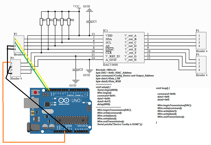
I want to control 10 bits DAC by Arduino using wire library.
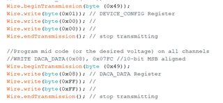
I read the data sheet of the DAC53608 carefully and wrote the following code to get 5 volts.

#include <Wire.h>
byte DAC= 0x48; //DAC_Address
byte command;//Config_Device and Output_Address
byte data1;//Data_LSB
byte data2;//Data_MSB


void setup() {
Serial.begin(9600);
Wire.begin();
command=0x01;
data1=0x00;
data2=0xFE;
delay(2000);

Wire.beginTransmission(DAC);
Wire.write(command);
Wire.write(data1);
Wire.write(data2);
Wire.endTransmission();
Serial.println("Device Config is DONE");

}

void loop() {

command=0x08;
data1=0xff;
data2=0xff;

Wire.beginTransmission(DAC);
Wire.write(command);
Wire.write(data1);
Wire.write(data2);
Wire.endTransmission();

}


```


```


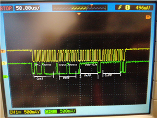
but there is no signal.
Does anyone face the same problem?

  • Hi,

    Can you please share your schematics? What is the reference voltage?

    Regards,

    AK

  • Thank you for your answer. Please see the image below

  • Hi,

    What is the voltage applied on VDD and VREF_IN?

    Regards,

    AK

  • Vdd= 5 volts..and tried with 3.3 volts

    Vref in = is open circuit and tried with GND and and Vdd

  • Hi,

    Connect VDD and VREF_IN to 5V and write the following. Also both /LDAC and /CLR should be pulled high.

    A0 should be high so that I2C address becomes 0x49 ( 7 bit address)

    1. address 0x01, device config register write 0x0000

    2. Next write DAC_DATA in any of the channel (for example, in address 0x08, write 0xFFFF.

    You should see approx 5V in channel 0.

    Regards,

    AK

  • Thank you so much for your reply.
    I tried your suggestion but unfortunately it did not work. I am really confused 

  • Hi,

    Please probe all the signals and make sure its correct

    /LDAC, /CLR and VREF and A0

    You need to change your address as 0x49, Your code was wrong, 0x01 should be 0x0000,

    Regards,

    AK

  • Hi,
    I probed the all pins, they are 5 volts (/LDAC, /CLR, VREF, Ao). 
    the code is as following:

  • Hi,

    Are the logic levels are correct from your controller?

    As per the screen shot, I can see max levels are 500mV only or scope has some attenuation set to?

    Regards,

    AK

  • yes it is correct, the value must be amplified 10 times so it is 5000 mV.

    Regards 
    Salam

  • Hi,

    Understood, Code wise everything looks fine to me. Can you read back the device ID to see the device responds to I2C commands?

    Regards,

    AK

  • first, I checked the address of the DAC by I2C scanner, when connected A0 to GND, I got 0x48 and when A0 connected to VDD, the address was 0x49.
    then I checked the response of the DAC when I sent the SCL  8 bits then waiting for ack signal from the DAC. if I enable the DAC, the ACK received but when the DAC is off, so there is no ACK then the controller does not send more SCL bits.

    Best Regards 
    Salam

  • Hi,

    This means device is responding correctly. What is the value of the capacitor connected to VDD and VREF?

    Please do the following debug. Instead of sending data to channel 0, try to broadcast the DATA by writing into 0x03?

    Also as debug, avoid the loop and put everything in void setup()

    #include <Wire.h>
    
    
    //I2C address definitions
    #define I2C_ADDR_ALO 0x49 //I2C address definitions
    
    void setup()
    {
    
      int MSB=0, LSB=0; //MSB, LSB variables for reading back registers
    
      Serial.begin(9600);
      Serial.print("Programming...");
      Wire.begin(); // join i2c bus (address optional for master)
    
      //Power-up the device and channels
      //WRITE DEVICE_CONFIG(0x01), 0x0000
      Wire.beginTransmission(I2C_ADDR_ALO); 
      Wire.write(byte(0x01)); // DEVICE_CONFIG Register
      Wire.write(byte(0x00)); // 
      Wire.write(byte(0x00)); //
      Wire.endTransmission(); // stop transmitting
    
      //Program 2.625V on channel A
      //WRITE DACA_DATA(0x08), 0x0868 //10-bit MSB aligned
      Wire.beginTransmission(I2C_ADDR_ALO);
      Wire.write(byte(0x08)); // DACA_DATA Register
      Wire.write(byte(0x08)); //
      Wire.write(byte(0x68)); // 
      Wire.endTransmission(); // stop transmitting
      
      Serial.println("Done");
      
    void loop()
    {
    
    }


  • the capacitor value is 0.1uF.

    do you mean? I should send 0x03 instead of config device ? or address of channel 0?
    like this?

    #include <Wire.h>
    
    
    //I2C address definitions
    #define I2C_ADDR_ALO 0x49 //I2C address definitions
    
    void setup()
    {
    
      int MSB=0, LSB=0; //MSB, LSB variables for reading back registers
    
      Serial.begin(9600);
      Serial.print("Programming...");
      Wire.begin(); // join i2c bus (address optional for master)
    
      //Power-up the device and channels
      //WRITE DEVICE_CONFIG(0x01), 0x0000
      Wire.beginTransmission(I2C_ADDR_ALO); 
      Wire.write(byte(0x03)); // DEVICE_CONFIG Register
      Wire.write(byte(0x00)); // 
      Wire.write(byte(0x00)); //
      Wire.endTransmission(); // stop transmitting
    
      //Program 2.625V on channel A
      //WRITE DACA_DATA(0x08), 0x0868 //10-bit MSB aligned
      Wire.beginTransmission(I2C_ADDR_ALO);
      Wire.write(byte(0x08)); // DACA_DATA Register
      Wire.write(byte(0x08)); //
      Wire.write(byte(0x68)); // 
      Wire.endTransmission(); // stop transmitting
      
      Serial.println("Done");
      
    void loop()
    {
    
    }

    Or like this

    #include <Wire.h>
    
    
    //I2C address definitions
    #define I2C_ADDR_ALO 0x49 //I2C address definitions
    
    void setup()
    {
    
      int MSB=0, LSB=0; //MSB, LSB variables for reading back registers
    
      Serial.begin(9600);
      Serial.print("Programming...");
      Wire.begin(); // join i2c bus (address optional for master)
    
      //Power-up the device and channels
      //WRITE DEVICE_CONFIG(0x01), 0x0000
      Wire.beginTransmission(I2C_ADDR_ALO); 
      Wire.write(byte(0x01)); // DEVICE_CONFIG Register
      Wire.write(byte(0x00)); // 
      Wire.write(byte(0x00)); //
      Wire.endTransmission(); // stop transmitting
    
      //Program 2.625V on channel A
      //WRITE DACA_DATA(0x08), 0x0868 //10-bit MSB aligned
      Wire.beginTransmission(I2C_ADDR_ALO);
      Wire.write(byte(0x03)); // DACA_DATA Register
      Wire.write(byte(0x08)); //
      Wire.write(byte(0x68)); // 
      Wire.endTransmission(); // stop transmitting
      
      Serial.println("Done");
      
    void loop()
    {
    
    }

  • Hi,

    I am assuming both pins have 0.1uF each.

    try this first.

    #include <Wire.h>
    
    
    //I2C address definitions
    #define I2C_ADDR_ALO 0x49 //I2C address definitions
    
    void setup()
    {
    
      int MSB=0, LSB=0; //MSB, LSB variables for reading back registers
    
      Serial.begin(9600);
      Serial.print("Programming...");
      Wire.begin(); // join i2c bus (address optional for master)
    
      //Power-up the device and channels
      //WRITE DEVICE_CONFIG(0x01), 0x0000
      Wire.beginTransmission(I2C_ADDR_ALO); 
      Wire.write(byte(0x01)); // DEVICE_CONFIG Register
      Wire.write(byte(0x00)); // 
      Wire.write(byte(0x00)); //
      Wire.endTransmission(); // stop transmitting
    
      //Program 2.625V on channel A
      //WRITE DACA_DATA(0x08), 0x0868 //10-bit MSB aligned
      Wire.beginTransmission(I2C_ADDR_ALO);
      Wire.write(byte(0x08)); // DACA_DATA Register
      Wire.write(byte(0x08)); //
      Wire.write(byte(0x68)); // 
      Wire.endTransmission(); // stop transmitting
      
      Serial.println("Done");
      
    void loop()
    {
    
    }

    Regards,

    AK

  • I really thank you for your help but unfortunately it does not work.
    I will try with Raspberry Pi 3 to see what happen.

    Best Regards
    Salam

  • Hi,

    Ok.

    Let me know the status.

    Regards,

    AK

  • Hi.

    Firstly, I connected the DAC with the Arduino and raspberry pi. and send the commands and got the same thing.


    All output channels give 16 mV without enabling commands of the channels.


    When I send the enable command to enable channel A, the voltage drops to 2.8 mV and others are still 16 mV. 
    And so on with enabling others channels but others channels drop to 0.2mV.

    When I turn off the DAC, everything comes back to the original states.

    I tried to read the register, there was no data always, received 0x0000.
    That means, in my opinion, the enable command works perfectly but the register doesn't receive any data from our code.

    Best Regards.

  • HI Salam,

    AK will take a look at this after the holiday weekend.

    Thanks,

    Paul

  • Hi Paul,
    Thank you so much,
    finally, it works.
    CLR ---> 5V
    Vref----> 5V
          

  • I would like to thank you for all your contribution, 
    finally, it works. 

    it must make these connections 


    CLR ---> 5V
    Vref----> 5V