This thread has been locked.

If you have a related question, please click the "Ask a related question" button in the top right corner. The newly created question will be automatically linked to this question.

TSW40RF82EVM: Waveform not the same in User Guide

Part Number: TSW40RF82EVM
Other Parts Discussed in Thread: ADC32RF80EVM, TSW40RF80EVM

Hello Team,

Good day. I'm posting this inquiry in be half of my customers, please see details below.

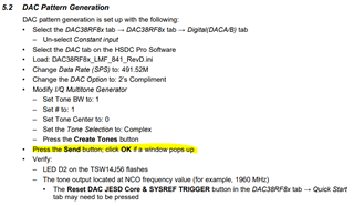
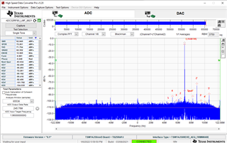
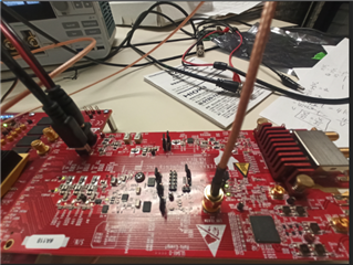
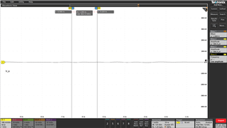
When I run this demo board according to the instruction slau706A(Page 3-4), the waveform shown in the scope is not correct. It is not 2dbm/1960Mhz sinewave


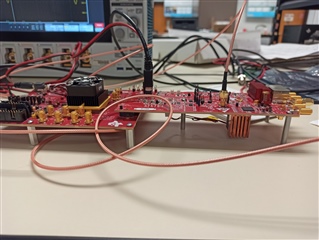
I use a 10MHz/2Vpp signal to connect to J12
I do it totally according to the instruction guide
I use rg316 as coaxial cable

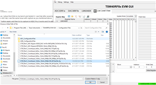
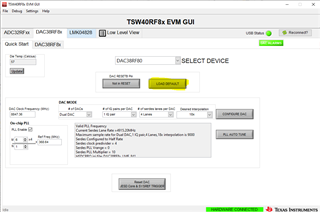
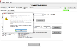
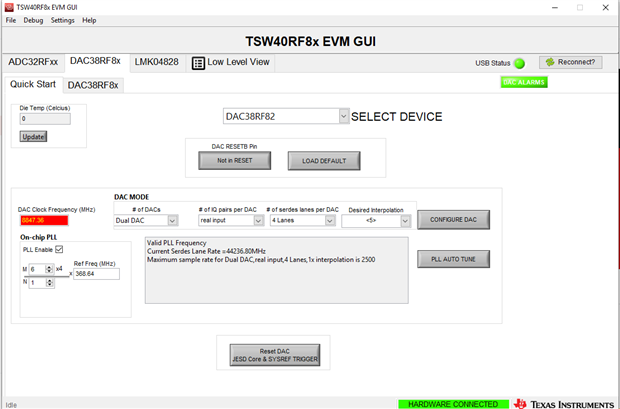
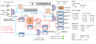
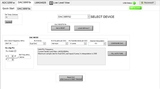
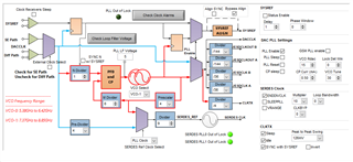
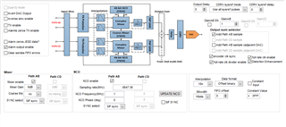
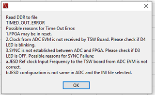
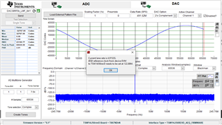
I also add the TSW40RF8x EVM GUI information below.

Regards,

Renan

  • Renan,

    In you DAC tab screen shot above, you have two invalid settings. The # of IQ pairs per DAC should be set to 1 IQ not real as you have shown. The Desired Interpolation should be set to 18x.

    Regards,

    Jim 

  • Hi Jim,

         But according to user guide, when I click "load default" button, and it switches back to option shown in above figure.

  • Maohang,

    Please see attached file. Are you doing this?

    Regards,

    Jim

     Page 4 of User.docx

  • Hi Jim, it still doesn't work. When I click load default option. Then the 'constant input' option automatically is chosen. 

  • I wonder whether it is caused by the 10MHz cable I use is not right? I use rg315 cable. One side connect to J13 with CMA connector. Another side connect to signal generator,

  • You must unclick the constant input manually using the GUI after loading the defaults.  

  • 10MHz needs to go to J12 not J13.

  • Yes. When I unlick constant input. The voltage is just 0 mv. There is not sin wave in the scope

  • And I just use scope instead of spectrum analyzer. J9 and J10 also aren't connected either.

  • And I just use scope instead of spectrum analyzer. J9 and J10 also aren't connected either.

  • What is the status of all LED's on both boards? After loading the configuration file, did you click on "PLL AUTO TUNE" on the Quick start page? If so, go to the DAC38RF8x Clocking tab and click on "Check Loop Filter Voltage" The PLL LF Voltage box should have a value between 3-5. Please send a screen shot of this along with a screen shot of the HSDC Pro GUI.

  • D4 & D5 are on. I click PLL AUTO TUNE after I click load default and unclick constant input, but the voltage is still 0.

  • D4 & D5 are on. I click PLL AUTO TUNE after I click load default and unclick constant input, but the voltage is still 0.

  • On the Digital (DAC A) tab, click on "Constant Input" and change the Data Format to "offset binary". There should now be an output that is the NCO frequency setting. If this is working, the issue might be the TSW14J56EVM. I need the LED status and screen shot I requested for this board as well. 

    If you do not get an output, you still have an issue with the TSW40RF82EVM. Make sure the 5V supply used by each board can source 4A. 

  • for TSW40RF82EVM: LED D6,D7,D4,D5,D10 are on.

    Do you mean I should handle HSDC? I don't turn it on. I just do it totally according to slau706A. It doesn't mention HSDC

  • This is the screen shot of TSW40RF82EVM

  • Do you get an output after doing this?

  • This is the result shown in scope. There is no sin wave.

  • Maohang,

    Please follow the attached instructions. This should give you an output. The configuration file you tried may have several errors in it. I am looking into this.

    Regards,

    Jim

    1057.DAC38RF82_NCO_Only_Test.pptx  

  • Hi, Jim it works right now. But when I increases the frequency from 100MHz to 1GHz, the waveform is totally distorted. Is it normal Phenomenon?

  • Did you click on "UPDATE NCO" after changing the frequency setting? You must do this every time you make a frequency or phase change when using the GUI. If you are monitoring this signal with an oscilloscope, you may exceeding the capability of the instrument at 1GHz.

  • Hi Jim,

         Yes and I click on the UPDATE NCO after changing the frequency setting. The DAC clock setting can be just 8847.36MHz which is not consistent with the one you mention in your power point-5898.24MHz. And the PLL LF Voltage is 7 at that time. My oscilloscope is 1GHz bandwidth which should be enough for 200MHz waveform. But the waveform is not good.

    50MHz NCO Setting:

    100MHz NCO Setting:

    200MHz NCO Setting:

  • Maohang,

    I just tested the NCO output procedure described in the Use's Guide and everything came up fine. Please verify your power supply can provide 4A. Not sure what might be causing your problem other than maybe a bad board. See file attached.

    Regards,

    Jim

    TSW40RF82EVM.pptx

  • Hi Jim,

        Maybe the external clock has some issue. Even when I want to do the ADC test according to page 5 on the slac706A . When I click the 'capture' function on HSDC according to the page 5, the error is as follows:

    I check the LED's, the LED4 is not blinking and it's off. Does it mean the external clock from J12 on TSW40RF82EVM board is not correct? I use 2Vpp/10MHz signal to connect to the j12.

  • Hi Jim,

        I have solved the DAC issue. But when I do ADC according to slac706a page5, the LED D4 is not blinking. 

  • I am having our ADC engineer look into this issue. 

  • Hi Jim.

        When I want to produce pattern generation according to slac706A(page7). When I finish the steps according to the user guide, the error shows as follows:

        I think there is still some issue.

  • Hi Maohang,

    This is not an error. It is an expected pop-up to inform the lane rate and clock expected by TSW14J56. You can click OK and continue.

    Also regarding the ADC capture issue, I setup this EVM on my bench and tested it. I see that after powering up and following instructions to LOAD DEFAULT, and configuring HSDC Pro ADC tab, I see the same issue with capture as you mentioned above.

    But if I click on the "LOAD DEFAULT" button again, and then try to capture in HSDC Pro, It works and I'm able to capture as below:

    Note that in some captures noise floor is higher than expected. This might be an issue with TSW platform as I don't see this on ADC32RF80EVM. 

    Regards,

    Vijay

  • HI Vijay,

        Do you mean after configuring HSDC PRO ADC tab, I should reload in TSW40RF8x EVM GUI as below? Then I reload the default software. But the error still exists and LED4 is still not blinking.

        Also, for DAC part, when I click sent and I can't see anything on scope. The voltage is always 0.

  • Hi Maohang,

    After setting up HSDC PRO ADC tab, go back to TSW40RF8x GUI and click on "LOAD DEFAULT" button and then return to HSDC PRO and capture.

    That procedure worked on my bench on 2 TSW40RF8xEVMs. 

    I will add Jim to this post to look into DAC issue. 

    Regards,

    Vijay

  • Hi Vijay,

        Yes and I load default again and the following error reports.

  • Hi Vijay,

        Also, I use the TSW40RF82EVM.Maybe the TSW40RF82EVM should be tested instead of TSW40RF80EVM.

    Maohang

  • This is just a warning, not an error. This should show up every time if using the DAC PLL. Remember, you must unselect "constant input" in the DAC digital tab every time after you load the config file to see output data from the TSW14J56.  

  • Hi Jim,

        Yes I unselect constant input every time. But when I click send command according to the user guide and  I use 'capture' function in my oscilloscope to check the waveform, there is nothing shown in the scope and the voltage is always 0v. 

        It should be noticed that I use TSW40RF82EVM instead of TSW40RF80EVM. And I also load the configuration file  "2T2R_RevC_ConstInput_12xDec_18xInt_2949p12M_4915p2Gb_TXClkOut-Div3.cfg".

        If I load the default file, even the NCO constant output is not correct. So I load the "2T2R_RevC_ConstInput_12xDec_18xInt_2949p12M_4915p2Gb_TXClkOut-Div3.cfg" file, and the NCO output is correct. But for pattern generation, there is no output under this situation.

  • Hi Jim,

       It suddenly works. And is there any method to make the pattern generation code not in cycle, and in stead makes it like pulse? 

  • Maohang,

    In the HSDC Pro GUI DAC tab, click on "Load external pattern file" and load the attached .csv file. This will produce two narrow pulses. After the file is loaded, click on send. You can edit these csv files to make any size pulse width you like. This example is a 4 sample pulse width for one channel and 2 sample pulse width for the other. Download the HSDC Pro User's Guide from the TI website for more information regarding loading and creating .csv test files.

    Regards,

    Jim

    4ns_pulse_CHA_2ns_pulse_CHB.csv  

  • Thanks and it helps a lot.