This thread has been locked.

If you have a related question, please click the "Ask a related question" button in the top right corner. The newly created question will be automatically linked to this question.

PSPICE-FOR-TI: What is the digital-side interface model for DAC8411 PSpice model

Part Number: PSPICE-FOR-TI
Other Parts Discussed in Thread: DAC8411, , TINA-TI

Hi,

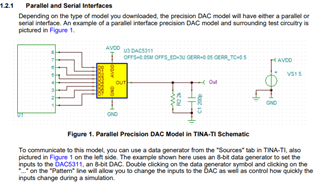
I was trying to build a 0-20mA current output DAC using the DAC8411 PSpice model. The DAC8411 model has a 16-bit parallel interface on the digital side. What is the best model that I could use for driving the DAC8411 igital interface? I am not able to find a 16-bit parallel ADC which I could use. The best I could get is ADC12break, but could not find any documentation and therefore could not find out what I should connect to the pins: CNVRT, STAT, OVER, REF?

  • Hi Sanjib,

    I am not familiar with the ADC12break model that you mentioned. You'd likely want to connect the REF to the same reference voltage that you intend to use for the DAC8411 so you won't have to scale the voltage you input to the ADC. If you share the part number I can probably let you know how to connect the remaining pins. 

    TINA-TI has a data generator source that can help you generate the signals for the parallel interface. I took a look, but I see this feature on PSPICE-FOR-TI.

    Best,

    Katlynne Jones

  • Hi Sanjib,

    I see the ADC model you are looking at now. I don't see any documentation for it though. It looks like the CNVRT signal is an enable for a new ADC conversion. I connected a pulse source to it and it looks like the 12 bit output is behaving correctly:

    I connected the 12 bits to the most significant 12 bits of the DAC and was able to roughly recreate the input voltage. You can mess around with the timings to get the results you are looking for. 

    I had the STAT and OVER pins connected to the 5V REF of the ADC and 5V AVDD of the DAC. I didn't notice a change when I grounded them.

    Best,

    Katlynne Jones