This thread has been locked.

If you have a related question, please click the "Ask a related question" button in the top right corner. The newly created question will be automatically linked to this question.

TLA2518: Issue Using Channel 0 as Digital Push-Pull Output - Output Stays HIGH

Part Number: TLA2518

I am having an issue with Channel 0 as a digital Push-Pull output.

When I configure Channel 0 to a Digital Push-Pull output it is always HIGH. I cannot set the output to a LOW level. I can successfully use the other channels (1-7) in this configuration. I have tried everything in regards to setting various configurations. I even lowered the clock speed down to 500KHz and placed delays in raising the chip select without success.

Any ideas on what is causing this issue?

  • Hello Robert,

    Are all the other channels also configured are GPIOs? these device is firstly an ADC, thus at least one channel needs to function as analog input, while the remaining seven can be GPIOs. 

    If this is not the case, would you please check functionality of Ch0 as digital output in Open drain configuration.

    Regards

    Cynthia

  • Hello Cynthia,

    Thank you for your reply.

    Here is my configuration:

    * Channel 0 - Digital Output (Push-Pull) --> does not work always HIGH

    * Channel 1 - Digital Input --> works correctly

    * Channel 2 - 7 - Analog Inputs --> works correctly

    I tested Channel 0 as a Digital Output (Open Drain) and Digital Input and it works correctly. 

    Also, Channel 1 - 7 as Digital Output (Push-Pull) works correctly as well, even if all of the channels are configurated as digital. I did not experience any issues if none of the channels were configured as analog inputs.

    Regards,

    Robert

  • Robert, 

    This is odd, I will try to duplicate this on my end, please allow some time for this. 

    In the mean time, I would like to confirm that you are programming it correctly, by programming the following registers: PIN_CFG Register, GPIO_CFG Register, GPO_DRIVE_CFG Register, GPO_VALUE Register

    Also are there any differences in how the channels are connected/driven?

  • Cynthia,

    Here are the values for the configuration registers:

    PIN_CFG = 0x03

    GPIO_CFG = 0x01

    GPO_DRIVE_CFG = 0x01

    As soon as I write to the GPO_DRIVE_CFG register the output goes HIGH. I even tried writing '0' to the GPO_VALUE register before and after the configuration and the output still goes HIGH.

    Robert

  • Robert, 

    I have tried duplicating this, and the CH0 does work correctly as a push pull.  I will point out that register GPO_VALUE (address 0xB) determines the value of the digital output, not the GPO_DRIVE_CFG register, thus it is odd that it does not respond. And this only happens when GPO_DRIVE_CGF is accessed for CH0, no other channel?

    Would you share the schematic with me to look over? Also, a scope shot of the communicates, including SCLK, CS, SDI and SDO

    Regards

    Cynthia

  • ~Edited~

    Speaking with some of my team mates, we have found a limitation on the device. 

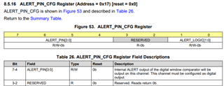
    The limitation concerns an ALERT of the digital window comparator function that is not supported on this device. The ALERT output is mapped to one of the analog input channels using a ALERT_PIN_CFG Register (Address = 0x17), which will need to be added to the datasheet. 

    This results that for this is device, if channel 0 is set as a digital output, then the digital window comparator will control the digital output, even if DWC_EN = 0. thus to control CH0 digital output using the ALERT_LOGIC field, of ALERT_PIN_CFG Register (Address = 0x17). see register breakdown below

    1. ALERT_LOGIC = active high; means digital output CH0 will stay low (because DWC_EN = 0)
    2. ALERT_LOGIC = active low; means digital output CH0 will stay high (because DWC_EN = 1)

    We apologize for the issues this oversight has resulted in. We are working on updating the necessary documentation to address this. 

    Regards

    Cynthia