This thread has been locked.

If you have a related question, please click the "Ask a related question" button in the top right corner. The newly created question will be automatically linked to this question.

ADS1261: Grounding scheme of ADC

Part Number: ADS1261

Hi,

We are using ADS1261 in our design. This is magnetometer and we have analog components also in our design. 

In the first prototype, we maintained single full ground plane for the board. We are getting noisy outputs from ADC output. We are suspecting it could be because both analog and digital components have single ground plane. And digital ground is noisy compared to analog ground.

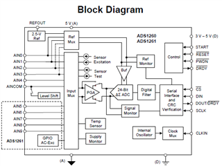
We are re-designing the board to split analog and digital ground. We also see this separation of grounds mentioned in a block diagram of ADC datasheet. Could you please let us know if this grounding scheme is good?

Regards,

Soumya 

  • Hi Soumya,

    As you noted, the ADS1261 datasheet does discuss using a split ground plane, so this is certainly possible. However, is there any way to be sure that this is the issue?

    Noise in the ADC output could be from many sources, so I am just confirming that you have eliminated all of these other sources of noise and can confidently say this issue is due to grounding? That would include intrinsic noise in the signal chain (amps, VREF, power supplies, signal conditioning circuitry, etc.) or extrinsic noise due to power-line noise (50/60Hz), EMI, RFI, poor layout or routing, etc.

    -Bryan

  • Hi Bryan,

    Yes we have eliminated all other sources. And we dont have any onboard SMPS.

    Also have one doubt regarding ADS1261 Evaluation board. Is it possible to turn ON the board using external power supply? Without USB power?

    Regards,

    Soumya

  • Hi Soumya,

    Yes it is possible to use an external power supply. Please review the Jumper and Switch Options in Table 3 in the ADS1261EVM User's guide, which tells you the jumper positions to disable the USB power and use external power supplies.

    -Bryan

  • Hi Bryan,

    Okay, thank you. I am little confused here. In Table 3, JP3 is for Digital power supply. JP4 is for Analog power supply source correct?But default is said as JP4 installed, but I didn't see JP4 installed on evaluation board. So just JP3 is enough to power evaluation board from external supply?

    Also we are trying to connect external source as we are seeing variations in ADC counts, will it help reduce if we power from external source?

    Thank you in advance.

    Regards,

    Soumya

  • Hi Soumya,

    Both JP3 and JP4 are not installed by default (the entire header, not just the shunt that goes on the header). You can confirm this in the Bill of Materials (section 5.1) and the Power schematic (Figure 19). The DVDD and AVDD power are shorted using resistors R94 and R95, which would need to be removed and then install jumpers JP3 and JP4 for external power (or somehow short pads 2 and 3 on the EVM itself). Then, a 5V supply can be connected to the "EXT_5V" net, which will provide 5V directly to AVDD and 5V to an LDO that then generates the 3.3V for DVDD.

    Let me know if this is the information you were looking for.

    I am not sure if powering from an external source will reduce the noise, this would depend on how noisy the external supply is. Are you using the ADS1261EVM for your design? I thought you already had boards built, and were just redesigning the ground plane?

    -Bryan