This thread has been locked.

If you have a related question, please click the "Ask a related question" button in the top right corner. The newly created question will be automatically linked to this question.

AD lead off detection configuration problem

Part Number: ADS1292R
Other Parts Discussed in Thread: ADS1292

Hi,

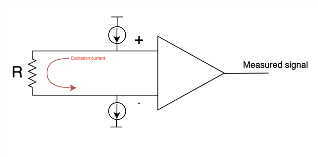
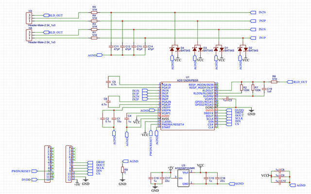
I'm trying to configure AC lead-off detection for my ADS1292R circuit prototype. I do not seem to see the effects of the AC current source in the measured signal. Here is the schematic:

I have enabled the AC excitation voltage and externally shorted the inputs positive and negative for Channel 1. I've configured the samping frequency to be 500 SPS, so I expect the AC excitation frequency to be 500 / 4 = 125 Hz. There are 51 KOhm series resistors in the input path as part of the anti-aliasing filter and I have configured the excitation voltage to be the max (22 uA), so I expect to measure a relatively large 125 Hz AC voltage at the channel 1 input, which should manifest as a large spike in the FFT plot. But I do not see this (note that a 1Hz highpass filter and 50Hz notch filter have been applied in software to these plots):

I'm hoping that it's just something I'm doing wrong in the configuration. The microcontroller sets the following register values before starting the continuous read mode:

CONFIG1 = 0x02

CONFIG2 = 0xE3

LOFF = 0x1D

LOFF_SENS = 0xF

CH1SET = 0x60

CH2SET = 0x60

RDL_SENS = 0x23

I have tested this setup by measuring ECG and EMG, and I have also managed to get the 1Hz test signal to work.

Is there something I'm doing wrong?

Thanks,
Matt

  • Hi Matt,

    Welcome to the E2E forum !!!

    I do not see any issue with the device registers setup for AC leadoff. The simplest method to check the AC leadoff is to let float both the electrodes and look at the device's output. To experiment with different electrode impedance, it is best to short the electrodes input to the common-mode voltage to ensure the device input common-mode voltage is set properly.

    Thanks

    -TC

  • Thanks for the response. When I let the electrodes float and look at the device's output, what specifically am I looking for? And when you say "short the electrodes input to the common-mode voltage", do you mean I should connect them to the output of the RLD circuit? I think this is the common mode voltage, since the RLDREF_INT bit of the RESP2 register is unchanged from the default so the RLD reference should be (AVDD - AVSS) / 2. But when I short the electrodes like this, there is still no spike in the measured FFT at 125 Hz.

  • Hi Matt,

    When the electrodes is left floating, you should see the maximum AC leadoff excitation at the frequency of fdr/4 on the ADC output. Please see the attached waveform below for the AC leadoff ADC output with the open electrode condition. You can verify this on the ADS1292 EVM board if you have one in your possession. 

    Yes, the common-mode voltage I refer to is the output of the RLD circuit ( (AVDD+AVSS)/2 ). 

    Thanks

    -TC

  • Thanks. Could you explain how the floating inputs results in the maximum measured AC voltage? My understanding is that the AC current flows from the positive electrode, through the patient, and into the negative electrode. I was under the impression that the differential voltage was genenrated in response to the lead-off current in accordnace with Ohms Law:

    So, if the inputs are left to float, the resistance R is effectively infinite so by Ohms Law the measured differential voltage will be zero. So when you say that floating inputs will produce the maximum AC voltage at fdr/4 Hz, this surprises me and makes me think I've misunderstood something. [Edit: This is incorrect, and Ohms Law does indeed dictate that the voltage will increase with increasing R]

    I'd appreciate any help you can give!

  • Hi Matt,

    When the input is floating, the AC leadoff current source will be charging and discharging the parasitic capacitance in the input pins at the frequency of fDR/4 to the power supply rail (AVDD for InxP and AVSS for InxN). Therefore, you will see the maximum AC amplitude in this scenario.

    Thanks

    -TC

  • Thanks. With your feedback about the expected behaviour of the device, I was able to configure it to output the desired 125 Hz signal. I have tested this by connecting the inputs to of Channel 1 to a potentiometer and I have observed that measured AC voltage at 125 Hz amplitude increases with increasing resistance. This will help to develop a system of estimating electrode impedance in the future. Thanks so much for your help!