This thread has been locked.

If you have a related question, please click the "Ask a related question" button in the top right corner. The newly created question will be automatically linked to this question.

ADS1114: ADS1114

Part Number: ADS1114
Other Parts Discussed in Thread: ADS1115

Hello,

I use 2 ADS1114 in I2C with a supply voltage of +5V. Both works because values, on serial interface, change in function of analog inputs.

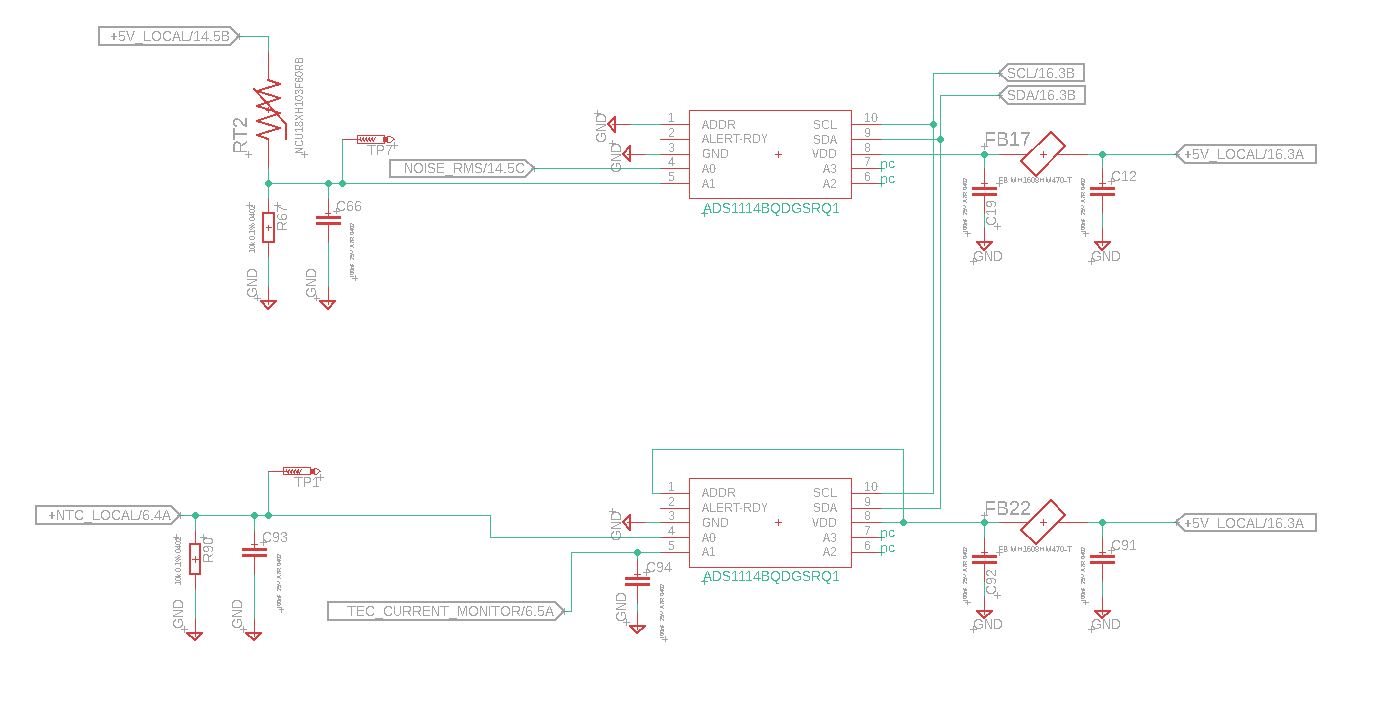
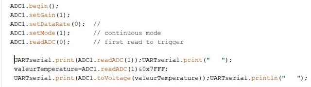
I use arduino with IDE interface to test this schematic. Below the code fot ADS1114 connected to the thermistor :

If I connect the input to ground, I've got wrong values :

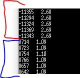
In red, it's thermistance values in decimal and voltage with the function ADC1.toVoltage( ) from arduino librairy. With multimeter, I have 2.54V in A0 pin.

In blue, it's when i connect the ground to the input. I don't have 0 but 8657.....

I have this problem with all ADS1114.

Do you have an idea?

Thank you best regards

  • Hello Romain,

    Are you intending to use the ADS1114 with SE or DIFF inputs? Based on the schematic you sent, it looks like differential since A1 input would need to be connected to GND for SE measurements. For the ADS with the thermistor, what is the input level at A0 (NOISE_RMS)? 

    It would also be helpful if you can share how the device is configured by sharing the value of the configuration register. 

    Regards,
    Aaron

  • Hello,

    No I don't want to do diff inputs, if I remember, it's not applicable for ADS1114. 

    Noise RMS is another signal from another function. It's not the same application than voltage from thermistor.

    For the configuration, I share all code row about ADS1114.

    Best Regards

  • Hi Romain,

    The ADS1114 allows for 1 SE input or 1 differential input. To measure a SE input, pin A1 needs to be tied to GND and the signal should be presented on A0. If you are still getting values, I wonder if the device is configured for differential inputs. Knowing the device config settings should help here. 

    Regards,
    Aaron

  • Hello,

    I thought that ads1114 have 2 inputs referenced to the ground. I checked the datasheet and it's really clear. Can you tell me, where on the datasheet you find this information, please?

    How the component can be configured in differential if I don't send the instructions by soft?

    Thank you best regards

  • Hi Romain,

    For the ADS1114, AIN0 is the positive input and AIN1 is the negative input. The multiplexer is not used in the ADS1114 and there is no connection to ground to get a single-ended measurement for two separate channels. To get a single-ended measurement out of the ADS1114, AIN1 needs to be tied to GND. 

    I have attached a snippet from the data sheet below that explains how to measure a single-ended signal. 

    It it possible to remove tie AIN1 to GND and apply the signals on AIN0 to check if the conversion results are as expected?

    Regards,
    Aaron

  • Hello,

    You right, it's only an input. 

    Thank you

    Best Regards

  • Hi Romain,

    Let me know if running the device in a SE mode provides correct readings. If you need multiple SE inputs, perhaps a device like the ADS1115 might be more suitable. 

    Regards,
    Aaron Estrada