This thread has been locked.

If you have a related question, please click the "Ask a related question" button in the top right corner. The newly created question will be automatically linked to this question.

DAC81404: Current Loop Output Configuration

Part Number: DAC81404
Other Parts Discussed in Thread: DAC8771

Hi,

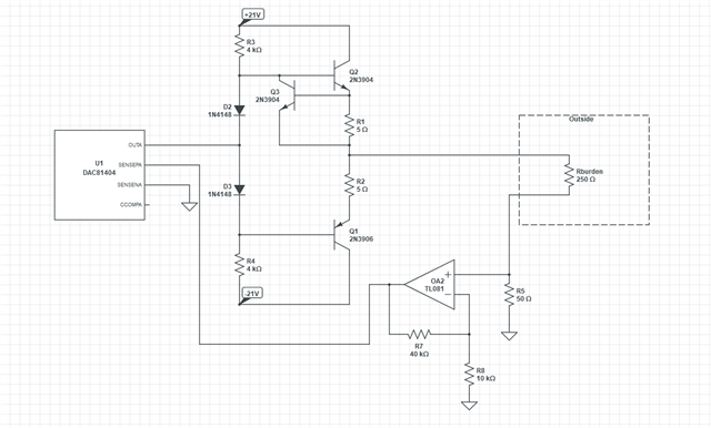
I want to make a +/-20 mA analog current loop driver with DAC81404. I'm planning to use a 50ohm shunt resistor that connected to sense lines through a opamp which has 5x gain.Thus, DAC will generate +-20mA in +-5V full scale range. Is this convenient method for this purpose or can you suggest different solutions? Also, I want to use high power stage with transistors like evaluation module design, can I use with my current drive approach?

  • Hi Ismail,

    Can you draw a quick schematic of how you planned to connect the op amp with gain of 5 to the sense lines? I do not understand how you arrived at your numbers with the 50Ω shunt. You will need the high power transistor stage because the DAC81404 can only drive ±15 mA on its own. The circuit from the EVM should work with your proposal. 

    Because your current requirement is lower, I will also mention that you could use the DAC8771 as well. It has a ±24 mA output mode.

    Best,

    Katlynne Jones

  • Unfortunately DAC8771 has single channel, I need to use 4 channel. Also this device works as a switch mode converter and I think DAC81404 will be less noisy than 8771.

    Sense line voltage should be full scale range voltage for max current output so, I picked 5x gain with opamp and I can use +-5V range of DAC. I attached schematic.

  • Hi Ismail,

    Got it, thank you for sharing your diagram. Is there a reason you wouldn't connect the sensep line to the top of your Rburden resistor? You would expect a voltage of ±5V at that node to generate the ±20 mA current through the 250Ω load. You would get the same result without creating the resistor divider and then gaining back the voltage across the shunt with the op amp. At full scale, the DAC output would be slightly above 5V to compensate for the high current output stage so the Rburden resistor sees 5V. 

    Your proposal would work, but I don't think its necessary. If you choose to go with it then you would need to change your Rburden resistor to 200Ω so you have a total of 250Ω when you include the 50Ω shunt. 

    Best,

    Katlynne Jones 

  • Rburden is out of my control, because that's another device's input resistance and it's variable. 250 ohm value is general usage of these resistors but it can be 50ohm, 100ohm, 1000ohm etc.. That's why I think 50 shunt resistor is needed. 

    My related question; If Rburden value is 1kohm, output voltage should be 20V. However, according to datasheet, there is no overrange for 20V scale. How can the driver reach the 20V with this circuit?

  • Hi Ismail,

    I understand your proposal now. The overrange feature is unrelated. It is an additional gain mode that can be selected in the DACRANGE register. It is not available for the ±20V or +40V scales because those scales require the DAC to be supplied with the max VDD and VSS. There would be no headroom to provide a 20% overrange for those scales.

    But, you are right that the DAC headroom will limit the required output if your Rburden increases to 1k. 

    You can add an additional high voltage amplifier with higher supplies to the output of the DAC to gain the input to the high current stage.

    Best,

    Katlynne Jones