This thread has been locked.

If you have a related question, please click the "Ask a related question" button in the top right corner. The newly created question will be automatically linked to this question.

ADS124S08: Questions on right schematic for Thermocouple application with CJC with the ADS124S08

Part Number: ADS124S08
Other Parts Discussed in Thread: ADS1248

Hello,

I am currently starting the development of a schematic based on the ADS124S08 for thermocouple (Type K) application. The intention is to use one ADS124S08 to read 5 Thermocouples and leave the additional channel for the CJC. As CJC I plan to use a RTD SMD PT100 (https://www.heraeus.com/media/media/hne/datasheets/smd/en_12/smd_0805_v_e.pdf) with obviously just 2 leads. I have looked for reference designs and I have seen 2:

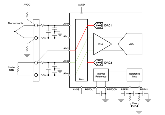
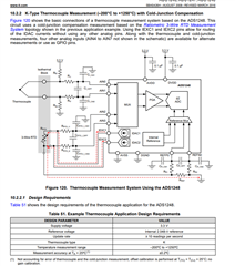
1) On one hand the reference design to be found for the ADS1248. In this case for a 3-lead RTD (page 83, see below):

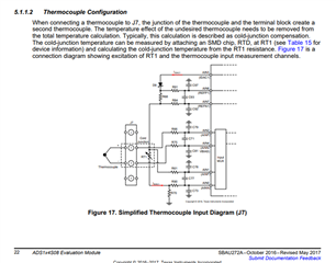
2) On the other hand a design in the ADS1x4S08 Evaluation Module (page 22 SBAU272A, see below):

As additional information to my application, I intend to use a single +3.3V supply between the AVDD/DVDD and AVSS / DGND (0V) and the internal reference only.

I see differences between both schematics, specially in regards to the use of IDAC1 only or IDAC1+2 and its connection to the RTD. Could you guide me a little bit and explain which should be the most suitable one to use as basis for my application and why?

Thanks,

Javier

  • Hi Javier,

    Welcome to the E2E forum!  If you haven't seen A Basic Guide to Thermocouple Measurements and A Basic Guide to RTD Measurements I highly recommend that you read through them and the example circuits.

    The thermocouple connection is rather straightforward.  However, the cold-junction measurement can be done a couple of ways with either a high or low-side reference.  As the RTD itself is 2-wire (just two connection points) you would use just one IDAC current source.  One specific example is shown in A Basic Guide to Thermocouple Measurements in section 2.8 on page 29.  

    Best regards,

    Bob B

  • Hi Bob,

    thanks a lot for your fast answer. I am reading the guide and understanding much better how to implement my needs. I have a fast question. If my understanding is correct, the ADS124S08 has 6 differential inputs (total 12 AIN). For each Thermocouple I would need 2, but for the RTD I would need 3, as the IDAC1 consumes one AIN, therefore with this ADC I would reach a maximum of 4 Thermocouples (not 5 as I was assuming) and 1 CJC. Is it correct?

    Do you see a way to get 5 Thermocouples and 1 CJC out of an ADS124S08 without external multiplexer?

    Best Regards,

    Javier

  • Hi Javier,

    The ADS124S08 has AIN0 through AIN11, AINCOM and REFP0 and REFN0.  AINCOM is the same as any other analog input or IDAC source.  So you could, as an example:

    • Connect 5 thermocouples to AIN0 through AIN9.
    • Connect the RTD across AIN10 and AIN11.
    • Excite the CJC RTD and reference resistor from AINCOM as the IDAC source.
    • Connect the reference resistor across the REFP0 and REFN0.

    Best regards,

    Bob B

  • Hi Bob,

    thanks again for your prompt answer. I think I came up with a design. It would be great if you could help double check:

    Design basis:

    5 Thermocouples (Type K) and 1 RTD (PT100) as CJC. As you have mentioned the IDAC1 routed over AINCOM.

    Boundary conditions of the application:

    - AVDD/DVDD/IOVDD = 3.3V

    - AVSS/DGNG = 0V

    - Max. SPS Thermocouples = 50. CJC to be able to reach 250SPS (after a TC read the CJC will be read always before going to the next TC)

    - Internal reference used for the Thermocouples

    Input Filter Thermocouples:

    CI_CM1 / CI_CM2 (uF) = 22nF

    CI_DIFF (uF) = 220nF

    Rin1/2 (Ohm) = 680Ohm

    Bandwidth diff. mode = 0.53 KHz > 10*50Hz (SPS Thermocouples)

    Input Filter CJC and Rref:

    CI_CM1 / CI_CM2 (uF) = 4.7nF

    CI_DIFF (uF) = 47nF

    Rin1/2 (Ohm) = 510Ohm

    Bandwidth diff. mode = 3.31 KHz > 10*250Hz (SPS RTD)

    TC Biasing resistors = 1MOhm (shall I increase to 10MOhm?)

    TC Voltage range = -6.5mV to 55mV (Type K TC)

    PGA amp. factor = 32

    Amplified TC voltage range = -208mV to 1760mV < 2.5V

    CJC (RTD)

    PT100 Max. resistance = 400Ohm

    PT100 Min. resistance = 18Ohm

    IDAC_1 current = 1mA

    Rref = 1.62KOhm

    Vref = 1.62V

    Vain3 = 2.02V

    Vain4 = 1.62V

    PGA amp. factor = 4

    Amplified RTD voltage range = 72mV to 1600mV < 1.62V

    0.75V < Vain4, Vain3 < 2.55 V

    Do you see any issues in the design?

    Thanks,

    Javier

  • Hi Javier,

    You might see some self-heating of the thermocouple with 1M resistors, so you may want to increase to 10M.  One other thing to note is the conversion time when switching the mux.  The fastest way to cycle through the mux is to use the low-latency mode digital filter.  However there is additional time required for setting up the conversion after a mux change as well as there is a programmable delay that can be used for analog settling of the mux when switching channels.  See the first conversion column in the datasheet table 13 on page 42. I would suggest looking at the Digital Filter tab in the ADS124S08 Design Calculator which can be downloaded from TI.com.  Using the calculator will help in determining the time for first conversion for helping to determine the required output data rate to capture all 5 thermocouples and CJC measurement for a particular cycle time.

    Best regards,

    Bob B