This thread has been locked.

If you have a related question, please click the "Ask a related question" button in the top right corner. The newly created question will be automatically linked to this question.

AFE5808A: Some questions about AFE5808A's application

Part Number: AFE5808A
Other Parts Discussed in Thread: , AFE5808

Hi Team,

Our customer is using AFE5808A and having below questions, can you help to answer them?

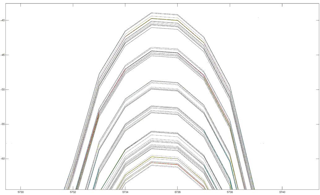
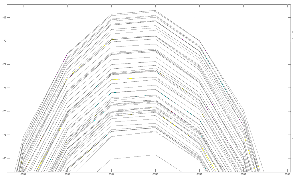
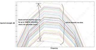
1. When using the same one signal input to multiple AFE channels, but we will see the difference on each channel's 2nd harmonic performance, sometimes it will have 8~20dB gap. Do you know what's the reason for this behavior?

2. Do we have any optimizing suggestion regarding to AFE's receiver saturation recovery performance?

3. Customer is considering to add inductor to discharge low frequency saturation signals on AFE receiver port, but as there is DC bias on AFE receiver port, it may need to pull up inductor to voltage source, do we have any ideas about this problem?

Thanks.

  • Thanks for helping the customer using AFE5808A.

    We will reply to you very soon.

    Thank you!

  • Hi,

    for the customer question:

    1. Please make sure if the customer has setup the following datasheet's register settings as:

    (please suggest the customers do this way if they did not. Thanks!)

    59[3:2]=01 and 52[12]=0 page 51 and page 53.

    2. Please see the Figure 56 and Figure 57 on page 28

    and from Table 15 page 60 see how Cbypass setting changes

    by using different INM value.

    3. In order to discharge low frequency we use high pass filter

    please look at page 30 Figure 59 section 8.3.1

    for example, if you use Cbypass=15pF

    then you could obtain a corner frequency about 100kHz

    (your low frequency signals will be discharged.)

    Thank you!

  • Hi Kung,

    Thanks for the feedback.

    Regarding to question 1 above, customer's setting is 59[3:2]=00, 52[12]=0. But they don't think it is related to 100kHz or 50kHz difference. Please refer to below 3rd harmonic performance for their 64 channels system. The first channel for every chip is on the top. They also mentioned it will see the similar behavior on our EVM, but it is relative better than on customer's board. Customer checked the layout, placement and power supply issues, but don't know the root cause. Is this related to our IC native behavior or others?

    Thanks.

  • Yes, the customer is correct. The 100kHz or 50kHz is not affect this customer's measurement.

    so please don't need to worry about the 59[3:2] bit settings.

    However, please the customer confirm about 52[12] bit setting?

    Either making 52[12]=0 or 52[12]=1 can make any differences for 2nd harmonic and 3rd harmonic better or no making any difference at all?

    If yes it can make difference, then how much difference has been made?

    Because from the pictures above, we cannot know what these pictures stand for?

    Thank you!

  • Hi Kung,

    For customer's current measurement, they set 52[12]=0. We will ask them to set 52[12]=1 to check the difference and feedback to you.

    Thanks.

  • Hi Kung,

    Customer reported another issue as below, can you also help to check what's possible reason?

    1. There is one chip having abnormal received data spike when enable HPF in register 0x15(=0009) and 0x21(=0009), other channels have no issues. But when disabled the HPF, no such issues. All channels have the same HPF settings. Do you have any insights for this problem?

    Thanks.

  • Hi,

    The picture shown from the customer is not clear to us.

    therefore, first, can the customer run the clock speed slowly

    such as 40MSPS?

    How the customer capture those data?

    Do they use AFE5808AEVM and TSW1400EVM to capture these raw data?

    Or they are using their own designed EVM board?

    We can see the spike from the first line of the attached plot.

    At the lowest level of the line, what is the captured data (number) is?

    also at the highest level of that line, what is the captured data (number) is?

    Thank you!

  • Hi Kung,

    Customer used their own board to capture these raw data and then used the Matlab to draw these pictures. They also checked on our EVM board, due to they can not feed all channel signals to the EVM, so they can only evaluate 1 or 2 channels, but will also see such 2nd harmonic and 3rd harmonic difference, but a little bit better than their own board.

    Regarding to the clock speed, currently they used is 50MSPS and fixed in their FPGA, and may not change to see the difference.

    Regarding to the plot meanings, take the below picture as example, please see the data explanation as below. So customer wants to check what's the possible reason for such HD2/HD3 difference on different channels?

    I also attached customer's schematic as below for input section for AFE5808, please also help to check if any issues, thanks!

  • Hi, Thanks for more information from the customer.

    Since the customer's PCB board has more signal wires connected to the input INP pin,

    therefore we need to assume the customer was only using TI's AFE5808AEVM and TSW1400EVM

    for the following discussions. Because the AFE5808A LNA input impedance (please look at data sheet page 62

    Figure 83) Zin calculation is only related to Rf (feedback resistance) without other traces or other components,

    also the customer needs to know the impedance can be changed by all kinds of values such as Rf value and Av(LNA gain) value

    and so on.

    From the customer's new HD2/HD3 plot (shown above),

    do it mean those channel-to-channel gaps are about 10dB range

    (by using register 0x34[12]=0, 0x3B[3:2]=00 or other) right?

    Because last time, the customer showed even about 20dB differences. Right?

    If this is correct, could you please ask the customer tried the following as well

    (by setting register 0x33[4]=0 as well). Thank you!

    If these can help the customer reduce HD2/HD3 readings, could you please let me know?

    Thank you!

    Since the customer cannot change their clock speed,

    could you please ask the customer change from 14-bit mode into 12-bit mode?

    If this test works or not, could you please let me know?

    Thank you as well.

    From the datasheet page 11, it shows HD2 = -60/-55dBc (typical)

    and also shows HD3 = -55dBc (typical)

    therefore if the customer can see better results than above

    than those are expected from chip to chip (from the datasheet point of view).

    Thank you for helping the customer.