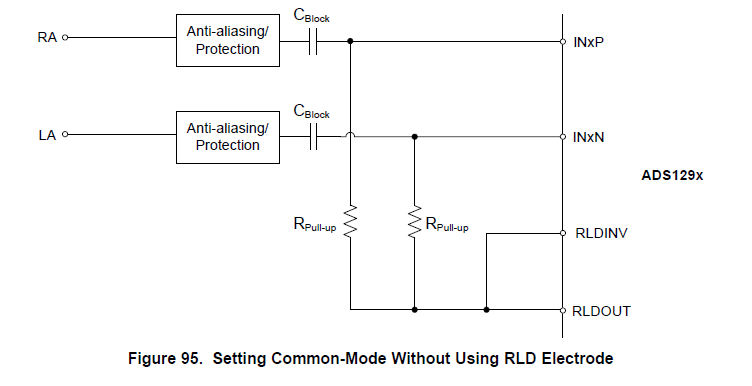
The RLD lead on the right side of the IC is suspended on the circuit. Only LL and LA leads are used to measure the ECG waveform, and the R-wave drift of ECG signal is found. See the picture for details. Please help analyze the reason.
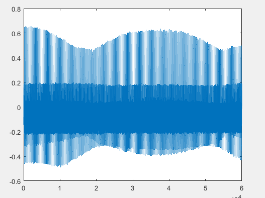
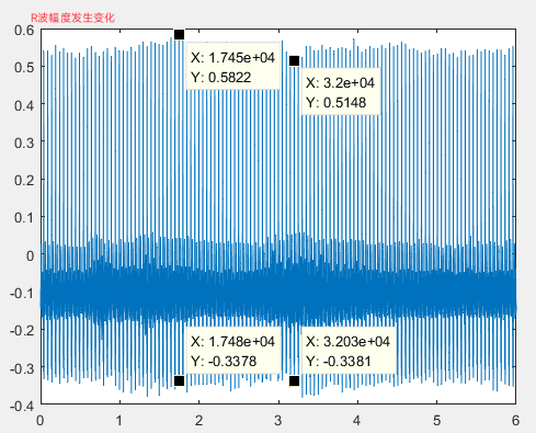
The RLD lead on the right side of the IC is suspended on the circuit. Only LL and LA leads are used to measure the ECG waveform, and the R-wave drift of ECG signal is found. See the picture for details. Please help analyze the reason.