Other Parts Discussed in Thread: ADS8688
Hey Sylvain!
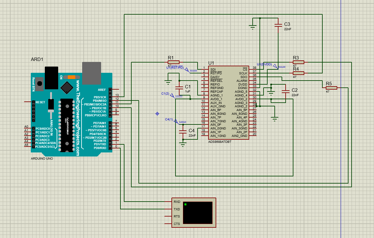
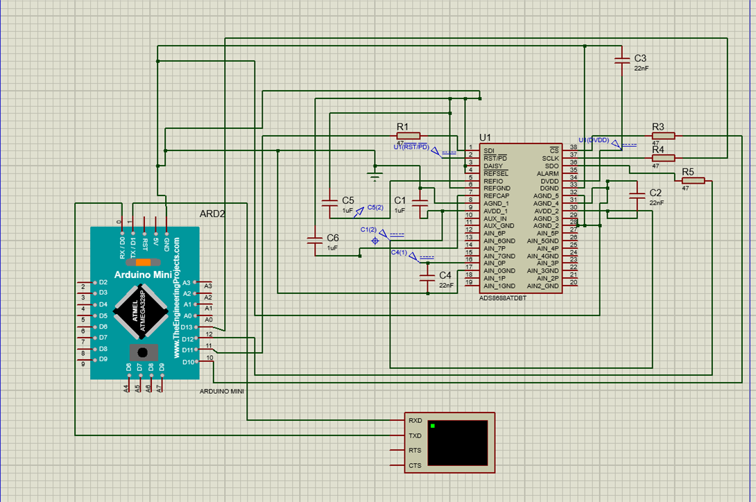
I am trying to simulate ADS8688a ADC on proteus which is coded on using arduino IDE using the library contributed by you on GitHub. I am hereby attaching the schematic being used.
We are trying to use an external clock from the microcontroller. When the code read_channel.ino from the example folder of Github is being executed, we are getting a full scale reading of 5.12V (0xFF) even though we are connecting a 3.7V source to AIN0P pin, AIN0_GND being grounded.
Could you please help us in trying to debug this asap?
Regards,
Amogh G
Code:
| /* ADS8688 library example | |
| * | |
| * PIN CONNECTION: | |
| * GNF: GND | |
| * REFIO: NC (output the 4.096V reference when REFSEL is connected to GND) | |
| * REFSEL: GND (enable internal 4.096V reference) | |
| * SDI: pin 11 / MEGA pin 51 | |
| * RST/PD: +5V | |
| * DAISY: NC | |
| * CS: pin 10 / MEGA pin 10 | |
| * SCK: pin 13 / MEGA pin 52 | |
| * SDO: pin 12 / MEGA pin 50 | |
| * ALARM: NC | |
| * AVDD: +5V | |
| * DVDD: +5V (Digital Logic Level) | |
| */ | |
|
#include <ADS8688.h> #include<SPI.h> |
|
| ADS8688 bank = ADS8688(); // Instantiate ADS8688 with PIN 10 as default CS | |
| void setup() { | |
| bank.setChannelSPD(0b00000010); // enable channel 0, power-down the others | |
| bank.setChannelRange(0,R6); // set all channel range to +- 1.25*Vref | |
| bank.autoRst(); // reset auto sequence | |
| Serial.begin(115200); // start serial communication | |
| } | |
| void loop() { | |
| Serial.print("CH0: "); // print label | |
| uint16_t val = bank.noOp(); // trigger sampling | |
| Serial.print(bank.I2V(val,R1)); // print value in Volts | |
| Serial.println(" V"); // print Volt label | |
| delay(500); // wait for 500 milliseconds | |
| } |