This thread has been locked.

If you have a related question, please click the "Ask a related question" button in the top right corner. The newly created question will be automatically linked to this question.

ADS7961: AUTO-2 operation mode

Part Number: ADS7961

Hi

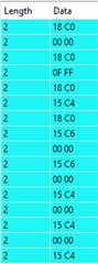
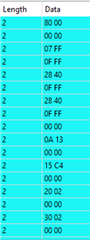
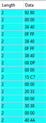
I'm trying to configure the ADS7961 to work in Auto-2 mode with a controller (FPGA) generating the following sequence to SDI (pin25):

  1. sending 0x18C0  ( setting to  manual mode , channel 1, x2Vref)
  2. sending 0x18C0  ( setting to  manual mode , channel 1, x2Vref)
  3. sending 0x18C0  ( setting to  manual mode , channel 1, x2Vref)
  4. sending 0x9280  ( setting auto-2 program register,   select channel 10 as the last channel)
  5. sending 0x3840  ( setting auto-2 mode register,   select  auto-2 mode)
  6. continuously sending 0x0000 and observing the  data recieved from SDO (pin 26)

Results :  the device  provides  data only from channel 1 , like it is stuck in channel 1, manual mode 

 (CLOCK speed is  50Khz)


Can you go through my configuration sequence  (steps 1-6) and explain what can be the reason for such behavior  ?

  • Hi Yoni,

    Can you send one more frame of 0x3840 and then send 0x0000? I believe Auto 2 mode may need one more frame before sending 0x0000. 

    Regards,
    Aaron Estrada

  • Thx Aaron

    I added additional 0x3840 before sending the first 0x0000 , data were provided sequentially ch0,1,2.3.......

    Issue now is that it scans all 16 channels , although my setting is for only the first 10 channels (0x9280)

  • Hi Yoni,

    The command 0x9280 looks like it should only set the first 10 channels. Let me go ahead and check this out on an EVM on my end and I will get back to you. 

    Regards,

    Aaron Estrada

  • Hello Aaron

    After reading other E2E issues on ADS7961, I tried other settings, but unfortunately I can't get the expected results per my understanding, in all settings  I received data only from channel 0 no matter what is my setting. 
    Can you go through my 3 setting and tell me what can be the reason for such behavior?

    I tried the following:

    Manual mode, channel 1:

    1. 0x18c0 - manual, channel 1, x2Vref

    2. 0x18c0

    3. 0x18c0

    4. 0x18c0

    5. 0x0000

    step 1-4 is done once, step 5 is done continuously 

    Result:  reading from channel 0 (instead of channel 1)

    Auto -1 mode:

    1. 0x8000 -  select auto -1 program register 

    2. 0x07ff  -  scan channel 0 to 10 

    3. 0x2840 -  Auto-1 mode

    4. 0x2840 - Auto-1 mode

    5. 0x0000

    step 1-4 is done once, step 5 is done continuously 

    Result:  reading from channel 0 (instead of sequentially  scanning all 10 channels)

    Auto - 2 mode:

    1. 0x9280  set program register , select  last channel as 10

    2. 0x3840  -  Auto-2 mode, x2VREF

    3. 0x3840 -   Auto-2 mode, x2VREF

    4. 0x3840 -  Auto-2 mode, x2VREF

    5. 0x0000

    step 1-4 is done once, step 5 is done continuously 

    Result:  reading from channel 0 (instead of sequentially scanning all 10 channels)

  • Hi Yoni,

    The commands look good to me. I went ahead and double checked the commands on an EVM and I had no issues reading only CH1 in manual mode and sequencing channels in Auto1 and Auto 2 modes. 

    For manual mode, you can see that I sent the commands you have above. You can see that after the 3rd 0x18C0 sent, the device starts to show CH1 conversion results. This is apparent by looking at the bits 15-12 and that they are 0001b. The rest of the bits are ~0x5C4 which shows 1.8V applied to channel 1 and I in fact have 1.8V connected to CH1.  So I was not able to observe a continuous CH0 reading. 

    In Auto 1 mode, I have the done  the same and sent the commands above. You can see that once I sent the first 0x0000 command, the device sends CH0 conversion results. After repeatedly sending 0x0000, the channels start to sequence in order up to CH10. After reading CH10 conversion results, the device resets to CH0 as expected. 

    For Auto 2 mode, similar behavior is observed as in Auto 1 mode. You can see the results below. The channels sequence until CH10 and then reset to CH0. 

    Since I am not able to reproduce the behavior you are experiencing, can you answer the following:

    • Are you using an EVM or custom board to evaluate the device?
      • If using a custom board, to you have a schematic available?
    • Is it possible to take oscilloscope captures of the SPI transactions for some of the modes?
      • If you can, can you also show emphasis on the timing of the SDI commands?
    • Do you have multiple devices available and if so, are you experiencing the same behavior on the other devices?
    • Is there any other devices on the SPI bus?

    Regards,
    Aaron Estrada

  • Thx Aaron

    At last  I found the root cause as loose power and ground connection.

    My master (FPGA) and slave ADC7960 are located on separate boards , power and ground connection between the boards were poor

    I had fixed this issue and it starts working as required in all 3 modes , so issue are close 

    In addition, I would like to know how much critical is the power-up sequence of +VA  (5V in my case) and +VBD(3.3V in my case) requirement,

    spec is mentioning  "The analog supply is always greater than or equal to the digital supply".

    What can be the impact when violating it  (permanent damage, wrong functionality...)?

  • Hi Yoni,

    I am glad to hear the issue has been resolved. For your supply question, it is hard to say what might happen and we can only speculate. These devices are very robust and I wouldn't expect there to be any damage to the device. However, there may be some unwanted leakage on the analog supply if the digital supply is powered up first. I would expect this potential leakage to dissipate when the analog supply is brought up. Again, this is an educated guess and leakage may not be present. 

    Regards,
    Aaron