This thread has been locked.

If you have a related question, please click the "Ask a related question" button in the top right corner. The newly created question will be automatically linked to this question.

ADS7961: Not able to communicate with ADS7961 using SPI.

Part Number: ADS7961

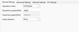
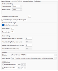
I've added snippets of code and SPI configs for review.

Please help as I'm new to this.

For loop in code snippet refers to the delay. We have tested the code with and without delay still we're not receiving any data in receive buffer.

	  uint8_t send_addr[4] = {0x10, 0x80, 0x10, 0x00};
      uint8_t receive_data[4] = {0};
	
	  //----------------xx MANUAL MODE xx --------------------------------------------------------------------
	  //------------------------------------------------------------------------------------------------------
	  DIGITAL_IO_SetOutputLow(&DIGITAL_IO_0);

	  //90,000 10ms
	  //9000 1ms
	  //100 ns
	//  for(uint16_t delay = 0; delay < 2; delay++);

	  SPI_MASTER_Transmit(&SPI_MASTER_0, &send_addr[0], 1);
	  while(SPI_MASTER_0.runtime->tx_busy);
	  SPI_MASTER_Transmit(&SPI_MASTER_0, &send_addr[1], 1);
	  while(SPI_MASTER_0.runtime->tx_busy);

	//  for(uint16_t delay = 0; delay < 100; delay++); //50ns

	  DIGITAL_IO_SetOutputHigh(&DIGITAL_IO_0);

	  //------------------------------------------------------------------------------------------------------

	  DIGITAL_IO_SetOutputLow(&DIGITAL_IO_0);

	  //90,000 10ms
	  //9000 1ms
	  //100 ns
	//  for(uint16_t delay = 0; delay < 2; delay++); //50ns

	  SPI_MASTER_Transmit(&SPI_MASTER_0, &send_addr[2], 1);
	  while(SPI_MASTER_0.runtime->tx_busy);
	  SPI_MASTER_Transmit(&SPI_MASTER_0, &send_addr[3], 1);
	  while(SPI_MASTER_0.runtime->tx_busy);
	  SPI_MASTER_Receive(&SPI_MASTER_0, &receive_data[0], 2);
	  while(SPI_MASTER_0.runtime->rx_busy);

	//  for(uint16_t delay = 0; delay < 100; delay++); //50ns

	  DIGITAL_IO_SetOutputHigh(&DIGITAL_IO_0);

	  //------------------------------------------------------------------------------------------------------

	  DIGITAL_IO_SetOutputLow(&DIGITAL_IO_0);

	  //90,000 10ms
	  //9000 1ms
	  //100 ns
	//  for(uint16_t delay = 0; delay < 2; delay++); //50ns

	  SPI_MASTER_Transmit(&SPI_MASTER_0, &send_addr[0], 1);
	  while(SPI_MASTER_0.runtime->tx_busy);
	  SPI_MASTER_Transmit(&SPI_MASTER_0, &send_addr[1], 1);
	  while(SPI_MASTER_0.runtime->tx_busy);
	  SPI_MASTER_Receive(&SPI_MASTER_0, &receive_data[0], 2);
	  while(SPI_MASTER_0.runtime->rx_busy);

	//  for(uint16_t delay = 0; delay < 100; delay++); //50ns

	  DIGITAL_IO_SetOutputHigh(&DIGITAL_IO_0);

	  //------------------------------------------------------------------------------------------------------
  • Edit : We're using digital output as Chip select pin.

  • Hi Gauri,

    Welcome to our e2e forum!  In this case, a picture is worth a thousand words.  Please provide a logic analyzer (or o'scope) plot of your /CS, SCLK, SDI and SDO lines.  It's much easier to understand what's going on versus trying to parse a snippet of code.

  • Hi Tom,

    Thanks for quick reply.

    It is not possible to provide a plot right now. Is there any other way I can test it out ? I will share the logic analyzer plot after some time.

  • Unfortunately, if you cannot observe you digital input/output, there is no 'good' way to validate that you have the proper operation of the device.  Send over the plots when you can.

  • We do not have an operating oscilloscope that is why I cannot provide you the plots.

    I'm reading channels from 0 to 5 in Manual mode where I'm getting correct results (verifying with first 4 bits if channel number) for CH0, CH1 and CH3. For CH2, CH4, CH5 we're getting incorrect data.

    Please refer to the table below.

    Channel No N frame Observed channel no in N+1 frame
    0 0
    1 1
    2 3
    3 3
    4 6
    5 7
    6 7
    7 7

    If we read CH0 (0x1000), we receive channel no as 0x0.

    If we read CH1 (0x1080), we receive channel no as 0x1.

    But when we read CH2 (0x1100), we receive channel no as 0x3 (incorrect) instead of 0x2.

    Is it necessary to add delays after CS low and before CS high (or at any other place) ?

    Please verify SPI configurations once.

    Thanks.

  • OK - so you can talk to the part and get conversion data, you just are not getting the expected results.  What mode are you using?  Do you get the proper CHID data running in manual mode versus Auto 1 or Auto 2?

  • I'm using Low if inactive, transmit on rising edge and receive on falling edge mode (which I think is mode 0).

    CHID is proper for few channels and not for others (please refer to the table above) in manual mode. I have not tested Auto mode 1 & 2.

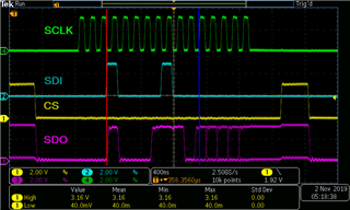
  • OK - try changing your phase setting, what you describe is Mode 1.  For the ADS7961, data is valid on the rising SCLK, changes on the falling.  In the following picture, the red line is where data is transmitted, received on blue.

  • Changing SPI mode just like you said did resolve our issue. Thanks you so much. Now we're using SPI mode Low if inactive, transmit on falling edge, receive on rising edge.

    We're are still receiving data that is less accurate (difference of a few volts than the actual voltage). How can I make it more accurate ?

    Also is any delay required such as inter frame delay or delay between chip select ? If yes, how much delay to add ?

    We're using XMC4700 with 144MHz clock so what SPI frequency would you suggest for high speed data transfer and accuracy ?

  • I would suggest that you follow the timing noted in the datasheet.  Without the capability to actually see your physical timing via o'scope or logic analyzer, it is difficult to provide suggestions.  As for accuracy of the conversion results, I would need to understand what your analog inputs look like.  Send over a schematic perhaps and we'll take a look.