This thread has been locked.

If you have a related question, please click the "Ask a related question" button in the top right corner. The newly created question will be automatically linked to this question.

ADS130E08: Getting READC mode working, and other things

Part Number: ADS130E08

I have some questions about this device, for which I have to write some software.

The most pressing is: I would like to use READC mode from a RaspberryPi RP2040 MCU (2x Cortex M0+) using DMA. I'm a bit new to directly using SPI as well.

Given that the SPI master unit uses max 16 bit values, how should I indicate a need for a read of the 24-bit status value? Is it sufficient to program 152 bits worth of data and munge it later? (I really wish it was only a 16 bit status!)

The SPI unit on the RP2040 is the ARM standard library part, PL021 SSP, and has a mode switch for Nat Semi MicroWire or Motorola SPI or TI synchronous serial. I presume I should be using SPI despite this being a TI made device?

I am also at a loss as to how to "ask" the ADC to send SCLK pulses for the read data at the correct time... the only thing I can think of is monitoring the DRDY signal from the ADC to trigger the DMA unit to request a fixed 152 bit frame from the ADC's SPI channel, which would in turn cause SCLK pulses to be sent which the ADC uses to transmit data.... is that right? I'm asking because basically none of the software I have seen code for actually implements READC mode, although some mention it.

  • Hello Ruth,

    Thank you for your post and welcome to our forum!

    Given that the SPI master unit uses max 16 bit values, how should I indicate a need for a read of the 24-bit status value? Is it sufficient to program 152 bits worth of data and munge it later? (I really wish it was only a 16 bit status!)

    Yes - you can program your MCU to read 152 bits every time the ADC completes a new conversion, which is indicated by the falling edge of DRDYn. The STATUS word and channel data can be parsed separately.

    The SPI unit on the RP2040 is the ARM standard library part, PL021 SSP, and has a mode switch for Nat Semi MicroWire or Motorola SPI or TI synchronous serial. I presume I should be using SPI despite this being a TI made device?

    I'm not familiar with the MCU you're using. However, the SPI that the ADS130E08 uses is not a synchronous interface. Instead, it is an asynchronous SPI protocol, which only communicates with the device when the DRDYn pulse triggers an interrupt-service routine in the MCU. You may find in your MCU that CSn needs to be manually controlled in order to keep the interface active throughout the entire 152-bit frame.

    I am also at a loss as to how to "ask" the ADC to send SCLK pulses for the read data at the correct time... the only thing I can think of is monitoring the DRDY signal from the ADC to trigger the DMA unit to request a fixed 152 bit frame from the ADC's SPI channel, which would in turn cause SCLK pulses to be sent which the ADC uses to transmit data.... is that right? I'm asking because basically none of the software I have seen code for actually implements READC mode, although some mention it.

    The SCLK pulses are an input to the ADC and come from the MCU. You are correct that you will need to monitor DRDYn and trigger an interrupt-service routine to read the data after each DRDYn falling edge. SCLK must be fast enough to complete the transaction in less than one data rate period.

    Can you clarify the mode you wish to use? Do you mean to say "RDATAC?"

    Regards,

    Ryan

  • Ryan thanks for replying. Sorry, yes I did mean RDATAC mode, and yes, I was just checking with you about synchronous serial. SPI it is!

    I can't find anything in the datasheet indicating the total conversion time, that is the time from when the ADC sample/hold captures the signal to when DRDY is activated. I would like to know it partly because the CPU is trying to track the current signal value, so it has to account for its input data being out of date.

    There is a value Tsettle that might be referring to this period, but at 1160 Tclk, it is ~5 times the period for an 8KHz capture rate, so I presume it only applies from Start to the next data conversion, not from subsequent conversions to the next. ... or is it perhaps pipelined, so it really is 566us delay but you get a new updated value every 125us after that?

    [As an aside, does that mean it is impossible to read using RDATA commands at more than about 0.9KHz? That's not at all obvious from the docs if so.]

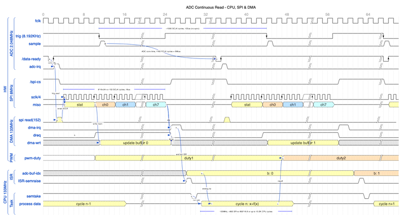
    I have created this timing diagram including both the hardware and software of the system, using 'wavedrom.com'. Does it look sane?

    The output is an integer to 'pwm-duty'. Please note SCLK is only showing every fourth clock pulse, and the adc data is double buffered, and the dma unit can be triggered from the drdy pulse and can dynamically reconfigure itself.

  • Hello Ruth,

    The ADS130E08 uses a delta-sigma ADC architecture. The sample-and-hold capacitor circuit is sampled and integrated over time. The result is a bitstream output which passes through a digital decimation filter. A high-resolution result is available from the digital filter at the data rate frequency. This ADC architecture is different than a SAR ADC, which converts the sample-and-hold voltage into a digital result with every conversion.

    The tSETTLE timing spec refers to the initial settling of the digital filter when conversions begin (i.e. START pin transitions from low to high). However, when there is a step change in the channel input voltage, this transition will appear in the ADC output after 3 data rate periods have passed (i.e. the fourth DRDYn falling edge indicates fully settled data).

    The RDATA command is used to update the output shift register with the most recently completed ADC conversion data on-demand. This is intended for applications which cannot read from the device at regular intervals and do not monitor the DRDYn interrupt. In RDATAC mode, if the host controller cannot finish reading the data before the next conversion is ready, the new data will immediately overwrite the previous conversion and the results will be corrupted. Using the RDATA command, the host controller can always read the most recent conversion reliably, but the risk is missing a sample.

    Regards,

    Ryan