This thread has been locked.

If you have a related question, please click the "Ask a related question" button in the top right corner. The newly created question will be automatically linked to this question.

DAC81408EVM: Internal Oscillator error

Part Number: DAC81408EVM

I have a question from a customer.

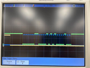
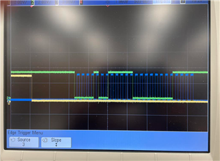
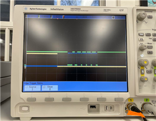
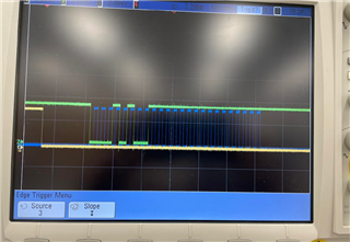
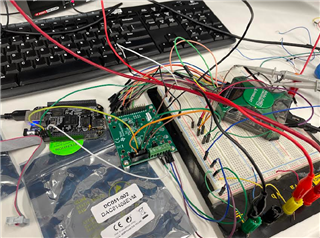
Hi, so I'm having trouble getting the DAC81408EVM to output anything when it's connected to an external master device (Protocol Analyzer on Analog Discovery 2). The DAC outputs correctly when I use the USB2ANY and GUI, but when I use the external device, the STATUS register gets an "Internal Oscillator Error" (OSC-ALM 0000000000001000). I'm connecting my external device to the CLK, MOSI, CS, and 3.3V pins on the J8 connector where the USB2ANY connector is supposed to go. I connected the ground to the TP2 ground pin. I assume that this shouldn't cause any problems, but I wanted to include it to be sure. I didn't include MISO or the other GPIO pins cause I assumed they weren't necessary.


My clock frequency on my external device is set to 8kHz. On the datasheet, it says that the serial clock frequency has a maximum 50MHz. I initially assumed that implied anything below 50MHz would also work, but I could be wrong.


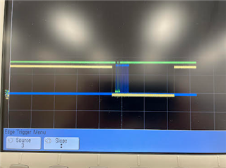
When I try sending 24 bit messages, the messages never send and are always zeroed out (according to the logic analyzer). What do you think I should do?

  • Hi Mark,

    I am trying to confirm the OSC-ALM bit with my team. This is not something defined in the datasheet, but was mentioned in the GUI as you saw. There is a similar device where the OSC-ALM bit does not indicate an oscillator error, so I want to double check if this bit actually indicates an error in this device.

    How are you reading the status register if you did not connect the MISO pin? Can you read the device ID register? 

    You are right that a clock of 8kHz should be ok. Can you elaborate on what you mean by "the messages never send and are zeroed out"? Can you confirm that you see the clock from your controller when you send a command? Try using just the oscilloscope with a rising/falling edge trigger on the Analog Discovery 2 just in case you have the protocol analyzer settings wrong. 

    Best,

    Katlynne Jones

  • Ok customer was able to follow up

    Hi Katlynne,
    Thanks for the response! When I use the USB2ANY GUI, the STATUS register indicates an internal oscillator error, but the DAC outputs voltages fine so I
    assume it's probably not an issue. Correct me if I'm wrong though.


    Please ignore the "zeroed out" portion of my question. That was an error on my part due to sending the data with an incorrect format on my Analog Discovery 2. However, I still see no response in my analog output after sending messages correctly with the Analog Discovery 2.

    My messages are:
    1) SPICONFIG = h030A84
    2) DACPWDWN: h09F00F
    4) DACRANGEn: h0CEEEE
    5) DAC0: h14FFFF


    When I use these messages with the GUI and USB2ANY, 2.5V appears on DAC0, and it works perfectly from there. However, nothing happens when I use the Analog Discovery 2.

    I used an oscilloscope to see my SPI output (CLK = blue, MOSI = green, CS = yellow)

    SPICONFIG = h030A84


    DACPWDWN: h09F00F

    DACRANGEn: h0CEEEE

    DAC0: h14FFFF

    The oscilloscope readings seem to match the messages according to me. Something I notice is that CS stays low for a significant amount of time after the
    MOSI has finished sending its data bits. I don't know if this is normal.

    Next, I connected the MISO pin like you suggested and tried to read from some of the registers. I don't think it really worked haha. These are the codes for the read messages I used:
    DEVICEID: 810000
    STATUS: 820000
    SPICONFIG: 830000
    GENCONFIG: 840000


    I creates these codes with this general format: 1b (read bit) + 0 (don't care) + 6 bit slave address + 16 don't care bits.
    The image below shows the responses I got to my read requests. The return messages didn't make sense, so I assume I didn't send the appropriate read
    messages.

    I've doubled-checked all my power supplies, and I've double checked all the connections to the J8 connector. So the GUI and USB2ANY must be doing
    something slightly different than my setup with the Analog Discovery 2. I'm not sure why it doesn't work.
    Here's a picture of my setup just to put it in context. Don't mind the microcontroller on the left—I'm simply using it to supply 3.3V to VIO at J8 and 5V to
    VAA/VDD at J7.

    Thank you again so much for your help!

  • Hi Mark, 

    I was able to confirm that the OSC-ALM bit is not an error bit. The description was added in the GUI before the register map was finalized. It actually indicates if the on-chip OSC is on or not – and during SPI readback it would always be on.

    I didn't catch that you were using the Analog Discovery 2 as your SPI controller. Your connections look ok from what I can see in the picture. Can you confirm that you have the ground of the microcontroller on the left connected to ground on your breadboard? Maybe that is where the green wire is going. 

    There is a minimum time from the last SCLK falling edge to the CS rising edge, but there is no maximum time that would indicate that the long delay you are seeing is an issue. It looks to me that the data is changing very close to the falling edge of the SCLK. The DAC reads the data on the falling edge, so the controller needs to update it on the rising edge. Try changing the you SCLK phase in the protocol analyzer to 1. 

    Best,

    Katlynne Jones

  • Customer was able to resolve the issue. Thanks Katlynne!

    //////////////////////////////////////////////////

    Wanted to let you know that I was able to get the BeagleBone to communicate with the DAC! It turns out the DAC operates in SPI mode 1—I had been using 0 until now. It's annoying—this fact wasn't in the datasheet. Anyway, thanks for all your help with this thing!

  • Hi Mark,

    Great to hear! I've seen variation in the naming of SPI modes between different controllers and that's probably why we don't specify which one to use in the datasheets. The important thing is that this DAC samples the data on the falling edge. The clock can idle high or low. So typically this would be SPI mode 1 or 2. 

    Best,

    Katlynne Jones