


Problem description
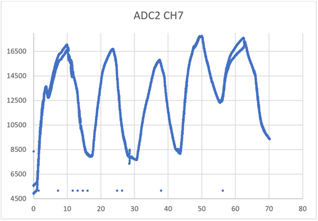
I am having issues with my thermocouple readings on my ADC. For the thermocouple readings of a single channel I have noticed that they often alternate from a slightly higher reading to a slightly lower reading, as per the figure below. This is not two different channel readings it is the same channel. The alternations/diverges appear to be symmetric around what the true value should be although I have not 100% confirmed this.
Below is an extract from another test showing how the value alternates each sample.
|
Time (uS) |
50380962 |
50390962 |
50400962 |
50410962 |
50420962 |
50430962 |
50440962 |
50450962 |
50460962 |
|
ADC value |
16937 |
16133 |
16942 |
16076 |
16930 |
16052 |
16908 |
16039 |
16876 |
Application description
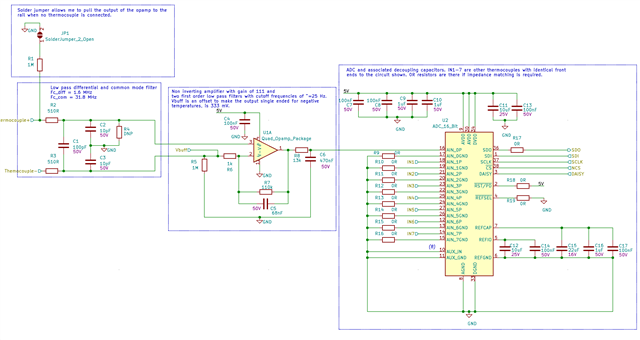
I am using multiple ADS8688 to sample thermistors, thermocouples and pressure sensors and then log them to an SD card. Below is an extract from my circuit diagram showing the thermocouple filter, amplifier and ADC configuration. The thermocouples are passed through a low pass differential and common mode filter before being amplified by a non-inverting amplifier with an offset (Vbuff) to allow the ADC to read negative temperatures.
The other ADC inputs for the ADC in the diagram are all thermocouples with identical front-end circuitry to the channel 0 example. My application has 4 ADCs with three of them in daisy chain configuration sampling each input at 100Hz and the other single ADC sampling each at 2 kHz. The only 2 kHz sensors are pressure sensors.
My sampling method is for a 100 Hz and 2kHz timer interrupt to trigger all channels to be sampled as fast as possible, so the actual sample frequency (the one the ADC MUX switches at) is much higher than 100Hz or 2kHz. My SPI clock line is running at 22.5 MHz. I have separate analog and digital 3V3 on the board for powering my MCU and DVDD for the ADCs as well as 5V for AVDD of the ADCS. I have a single ground for both analog and digital signals.
The purpose of the DNP R4 resistor is because I was not sure how to correctly ground the thermocouple leads (This is my first time working with thermocouples so I was leaving my options open once the board was manufactured).
Further problem examples
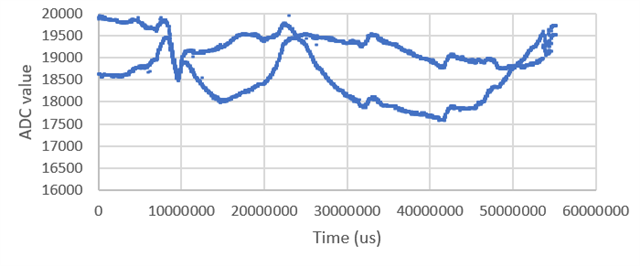
The divergences do not happen every test and can happen for short or long periods, such as the example below. The X axis is time in seconds and the Y axis is ADC value of a single channel (Sorry I forgot to add these when running this test).
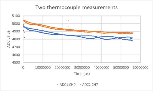
It occurs on all thermocouple channels and temperatures, while not "diverging" at the same time or by the same amount, such as the below example showing two thermocouple readings:
This error does not occur in my pressure or thermistor readings. The only differences between them and the thermocouples (other than not being thermocouples) are:
- The thermocouples are amplified by a gain of 110 which the other sensors go through unity gain filters.
- The thermocouples have an offset voltage Vbuff (333mV) involved in their amplification while the pressure and thermistors do not. This voltage should be steady as it it created by a voltage divider to 333 mV from a 1V shunt reference that then gets passed through a voltage follower.
- Thermocouples have low pass differential and common mode filters.
Things I have tried
- My application requires spare thermocouple channels so that they are available if the requirements change. When a thermocouple is not connected to a spare channel I am driving the output of the non-inverting amplifier in the circuit diagram above low by connecting the positive thermocouple node to ground through a large resistance and solder bridge. I have tried grounding/not grounding all other inputs on an ADC using this method and I still get the error on the channel with a thermocouple in both cases.
- One of the ADCs in the daisy chain samples thermocouple, thermistor and pressure sensors at 100Hz. The error is not present in the pressure sensors or thermistors.
- I have tried different channels on the ADC. All show the error.
- I have tried measuring low and high temperatures, no visible pattern.
Current theories
Below is a list of the thoughts I had of what it could be, although I am clutching at straws and don't have much foundation for these ideas:
- No separation of analog and digital grounds.
- Not having 100 nF capacitors between positive and ground ADC inputs, although I thought this would cause errors in the pressure and thermistors too.
- Reaching the gain bandwidth of the opamps? Not sure what this would do but I am aware that 110 is a relatively high gain.
My best idea is its something to do with having large amplification but any help would be greatly appreciated! Let me know if there is any other testing/data/information you would like sent through if needed.
Cheers.

