This thread has been locked.

If you have a related question, please click the "Ask a related question" button in the top right corner. The newly created question will be automatically linked to this question.

ADS7953-Q1: Configuration Failure

Part Number: ADS7953-Q1
Other Parts Discussed in Thread: TMS570LS1227

Hi,

Some of our control boards that use above mentioned part are failing configuration for Auto-1 mode. Although it works fine on the remaining boards. We are trying to figure out if there is some problem in our start-up configuration or did we have a faulty batch? Following are the SPI commands sent at 2ms interval:

0x4200 (reset device and its register)

0x0000 (wait to make sure registers have been reset)

0x2840 (auto-1 mode, programming enabled, counter increment, 5V range, normal operation, channel address on SDO)

0x0000 (continued operation in auto-1 mode)

last command is sent at 2ms time interval to keep operating in auto-1 mode. In the faulty control-board, we've observed that channel address is not getting incremented. After forcing auto-1 configuration multiple times, it does start working randomly. But our concern is that we want robust configuration routine. Can you please confirm that above SPI configuration is correct? Is there any potential problem? We've also scoped the signals and waveforms appear consistent with the commands sent. 

Best Regards

Nouman Sadiq


  • Hi Nouman,

    The commands look good to me. As a sanity check, I went ahead and checked them out on an EVM here on my end and the results are below:

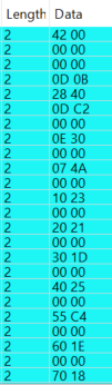
    You can see that the channels cycle accordingly. 1.8V was applied on Channel 5 and the code 0x5C4 is expected in 2xVref mode. Have you tried to check if the abnormal behavior follows the device or the board? To check, you can swap a 'bad' device on a 'bad' board with a known good device from a known good board and vice versa. This should allow you to check if the behavior follows the device or the board. 

    Regards,
    Aaron

  • Hi Aaron,

    Apologies for the late reply. I work together with Nouman in this issue. We have swapped the "bad" device from a known "good" board and now it is working as expected. We first thought it was a bad device but since, we've had the same issue in several other boards (and from different batches), so we think this is less likely. Is it possible that we are playing right within the tolerances of some parts of the device (maybe some comms) which is why it works for some devices but not others? We have been checking timing requirements for the SPI comms and haven't found anything wrong with it. Do you have any idea of what might be wrong? Any help/idea would be much appreciated.

    Some extra information about our system is we are using at TMS570LS1227 with its MiBSPI to communicate to 2 separate chips. One is this one and the other one is the PSU TPS65381AQ. They share SDI, SDO and CLK signals but obviously each of them have their own CS signal.

    Regards,

  • Hi Javier,

    No worries on the response time! So just to be clear, you swapped out a 'bad' device with a known 'good' device and there are no issues? If so, then the behavior seems to follow the device. It is very possible that the timings could vary and that could cause some communication troubles but if they are within data sheet specs, I wouldn't expect any unexpected behavior. I know you have already looked into the timings but if you can share some scope shots of the communication lines, that would be great. Preferably with all of the SPI lines on the same capture and the time scale small enough to make out the timings. 

    Do you also have a schematic to share? If you are not comfortable sharing publicly, you can always send me a friend request and you can share it privately. One more thing... if you can grab a picture of the IC top markings from some of the 'bad' devices, that may be helpful as well. 

    Regards,
    Aaron 

  • Hi Aaron,

    Thanks for the quick response. I have sent you a friend request to share the schematics.

    Regards,

  • Hi Javier,

    Thanks for the friend request. We can take the conversation privately.

    Regards,

    Aaron

  • Hi Aaron,

    I think we have found the problem. It seems we were using the SPI clock signal without delay (CPHA = 0 ) but the ADC requires this to be 1 (It samples on the rising edge of the clock). It is a bit surprising that with those settings we had previously the communication worked at all but it seems that small differences in tolerancing between different devices was enough to make it work in some circumstances and the required hold time between stable SDI and rising edge of the CLK is so small (3-4ns) that for some devices it was ok. We have now changed it and got it working reliably.

    Thank you very much for your quick support, much appreciated.